Site pages
Current course
Participants
General
MODULE 1. Introduction to mechanics of tillage tools
MODULE 2. Engineering properties of soil, principl...
MODULE 3. Design of tillage tools, principles of s...
MODULE 4. Deign equation, Force analysis
MODULE 5. Application of dimensional analysis in s...
Module 6. Introduction to traction and mechanics, ...
Module 7. Traction model, traction improvement, tr...
Module 8.Soil compaction and plant growth, variabi...
LESSON 6. MECHANICAL PROPERTIES OF SOILS
6.1. INTRODUCTION
Soil is a granular medium that varies in composition from organic peat to gravel and that may contain various amounts of water. The soil physical system is continually being subjected to external forces and is, therefore, dynamic. These external forces may be environmental (climate, plants, animals, and micro-organisms) or mechanical (forces applied by man using some type of machine). The specific reaction of the soil to these forces is of interest. The forces provide the means for changing soil from one condition into another and the reaction indicates the kind and degree of change. If one is to be able either to maintain a soil condition or to change it to a more suitable condition, he must first have an understanding of soil behavior; this behavior must eventually be properly described. Soil conditions and properties, widely varying types of forces, and widely varying types of behavior must all be included in any description before the description can be satisfactory.
i. Shear strength
If a soil specimen is subjected to shear stress, the shear stress-strain diagram may look like one of the curves in Figure 2.1, depending upon the soil conditions. A highly cemented soil will result in a well defined failure point as shown by curve A. Loose soil may not show any definite failure point and the stress may increase exponentially with strain reaching some maximum value as shown by curve B. Curve C is for a soil that is well compacted but not cemented.
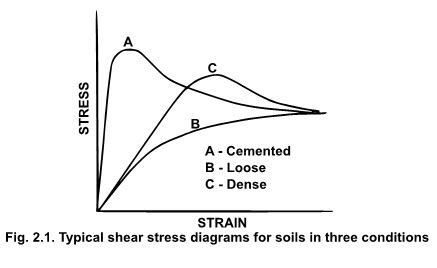
The soil strength refers to the value of the shear stress on a plane within the soil sample where soil failure has taken place either by rupture or breakage. For curves A and C this point is clearly defined but for curve B soil failure is not distinct. In the case of curve C the failure is considered to have taken place by yielding or plastic flow and the asymptotic value of shear stress is taken as the shear strength for this case. The shear stress-strain curves shown in Figure 2.4 are for a given normal stress on the sample. If the normal stress is changed, the shear stress-strain diagram will change and consequently the value of the maximum shear stress will also change. An increase in the normal stress would cause an increase in maximum shear. Therefore, the shear strength is a function of the normal stress on the failure plane.
Mohr-Coulomb failure theory states that failure in a material occurs if the shear stress on any plane equals the shear strength of the material. Furthermore, the shear strength (s) along any plane is a function of the normal stress (σ) on the plane, as shown below:
s = f (σ) -------------------------------------- (2.9)
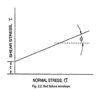
Coulomb, in 1776, conducted experiments to determine the maximum shear stress that could be applied on a plane within a sample of soil at varying levels of normal stress. He plotted the maximum shear stress values at failure against the corresponding normal stress on the failure plane and suggested the following linear relationship:
τ = c + σ tan(Ø) ---------------------------- (2.10)
where, τ = shearing stress at soil failure
c = cohesion
σ = stress normal to plane of shear failure
Ø = angle of internal friction
The Coulomb criterion is shown as a straight line in Figure 2.5, with an intercept on the shear stress (τ) axis equal to c and a slope equal to tan φ. The quantities c and f are material properties frequently called cohesion and angle of internal friction, respectively. The shear strength as defined by Equation 2.10 represents the maximum shear stress that may be sustained on any plane in a given material. The strength function is called the failure envelope since it defines the limiting stress.
Field measurements of soil shear strength.
The direct shear and triaxial shear tests are laboratory procedures to measure the shear strength. Soil samples must be taken from the field to perform these tests. The samples may get disturbed and their shear strengths may be altered in the process. To avoid this, field methods to measure the shear strength have been developed. The first method is a round shear box which is rotated after it is inserted into the soil as shown in Figure 2.10. The box is driven into the soil until the top of the box is in contact with the soil surface. The soil is excavated carefully outside the box before applying the torque to shear the soil. The soil at the bottom of the box is sheared. The shear strength is calculated using the following equation:
![]() --------------------------------------- (2.11)
--------------------------------------- (2.11)
where,
s = soil shear strength
M = moment at failure
r = shear box radius
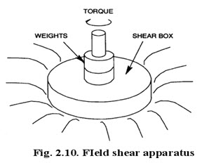
Markers are placed on the soil inside the box that are visible through small holes in the top of the box. The markers are used to ensure that the soil shears uniformly.
To overcome the problem that the soil located near the outer edge of the shear box must move considerably farther than that near the center, a narrow annulus has been designed as a shear box. Shear strength for the narrow annulus shaped box is calculated from the following equation:
![]()
where, r1 and r2 are the inner and the outer radii of the annulus, respectively.
The field apparatus described above requires excavating the soil at the outside after inserting it into the ground. A vane type apparatus as shown in Figure 2.11 does not require excavation.
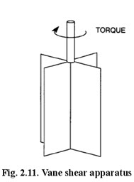
Once driven into the soil the rotation causes shear of soil along the surface of the cylinder that is generated by the vanes. This device may be used at greater depths. Measurements can be made at increasing depths without extracting the shear device so that a rather complete strength profile of natural soil conditions can be obtained. The vanes have a height-to-radius ratio of 4:1. The vane shear apparatus provides no means of varying normal load. Shear strength is computed as:
![]()
where, r is the radius of the circle inscribed by vane tips.
ii. Friction
All tillage operations involve a sliding action of soil over some surface of the tool. Friction of soil against a tool having large contact areas represents a significant component of the draft requirement. Friction is also involved when two rigid bodies of soil move with respect to each other.
Hence, there are three types of frictional parameters in problems involving soil dynamics. These are soil metal-friction (μ′), soil-soil friction (μ), and soil internal friction (tan φ). Soil internal friction (tan φ) has been discussed in reference to soil shear strength in equation 2.10. To determine soil-soil friction and soil-metal friction, we make use of Coulomb’s concept of friction coefficient,
![]()
µ = coefficient of friction (soil on soil)
µ’= coefficient of friction (soil metal-friction)
F = frictional force tangent to the surface
N = normal force (perpendicular to the surface)
ψ = friction angle
iii. Adhesion
Adhesion is defined as the force of attraction between two unlike bodies. In soil, adhesion is due to the film of moisture between soil particles and the surface contacting the soil. The force of adhesion is due to the surface tension of water and consequently it depends upon the value of surface tension and moisture content of the soil. However, it is virtually impossible to differentiate between friction and adhesion. Thus, an apparent coefficient of friction is often used to include effects of both friction and adhesion. Figure 2.13 shows the effect of moisture content on the apparent coefficient of friction.
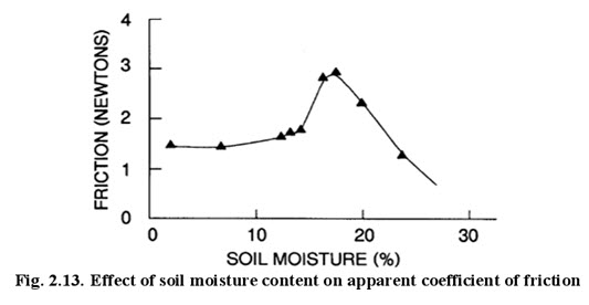
It can be seen that initially at low moisture content the friction is due to pure sliding action. As the moisture content increases, friction increases due to increased adhesion. As the moisture content is increased even further the friction reduces due to the lubricating effect created by the moisture film. The following model has been proposed to include adhesion:
F = aCa + N tany --------------------------------------- (2.15)
Where,
Cα = adhesion and
a = surface area.
iv. Abrasion by soil:
Abrasiveness is a dynamic property of soils that has a cumulative effect rather than an immediate effect. When a large amount of soil slides over the surface of a tillage tool, abrasive wear may change the size, shape or roughness of the tool enough to make it ineffective, especially if soil pressure against the tool are high. Soil characteristics or conditions that effect abrasiveness includes hardness, shape and size of the soil particles, the firmness with which the particles are held in the soil mass and the soil moisture content. The abrasive resistance of metals is influenced by its hardness, strength and toughness.
A layer coating of a special, abrasion-resistant alloy is often applied along the cutting edges of tillage tools to reduce wear rates, especially for operation in sandy and sandy loam soils. This process is known as hard facing or hard surfacing. Hard facing materials of different compositions are available for specific combinations of abrasion and impact conditions. These materials sold under various trade names are extremely hard and some are quite brittle. They are generally nonferrous, chromium-cobalt-tungsten alloys, or high-carbon iron base alloys containing such elements as chromium, tungsten, manganese, silicon and molybdenum. They are applied to plowshares, subsoiler points, chisel cultivators and other tillage tools by means of electric arc or an acetylene torch.
v. Compressibility
Failure of a soil by compression is generally associated with a reduction in volume. Failure in shear and failure by compression are not independent phenomena, but occur as some combined action. Failure or yielding of a soil can also be evidenced as plastic flow without the usual shattering and developing of shear failure surfaces. An example is a “flowing” of a wet clay soil around a subsoiler shank as the tool moves through the soil.
vi. Erodibility
Fine grained materials are easily transported, but clays are difficult to initially erode due to cohesion.
vii. Permeability
It is defined as the ease with which water flows through the soil. Fine grained materials are less permeable.
viii. Corrosion
It is defined as the tendency to corrode materials and structures, esp. metals, laid in the ground.
Last modified: Wednesday, 12 February 2014, 9:27 AM