Site pages
Current course
Participants
General
MODULE 1. Introduction to production of agricultur...
MODULE 2. Advance in material for tractor and agri...
MODULE 3. Advanced manufacturing techniques
MODULE 4. Heat treatment of steel
MODULE 5. Industrial lay out planning and quality ...
MODULE 6. Economics of process
MODULE 7. Techno economic feasibility of project r...
MODULE 8. Servo motors, drives and controllers
MODULE 9. CNC controllers for machine tools
MODULE 10. CNC programming
MODULE 11. Assembly and plant automation storage a...
LESSON 22. CASE STUDY OF MANUFACTURING OF WEEDERS
3.0 Introduction
Weed control in irrigated and rain-fed agriculture during kharif is a serious problem and the yield is affected to the extent of 20 – 60%, if timely control is not carried out. Availability of good welders has been the major constraint for the farmer. Self propelled and power operated welders are being introduced on limited scale. Majority of farmers continue to use hand tools for weeding.
The manual welders are mostly manufactured by small scale manufactures who doesn’t have adequate facilities and complete know-how about the material, heat-treatment and production process to maintain proper specifications. Efficient working of the welders and specially the performance of critical components like blade depends a lot on proper material and manufacturing process.
The manufacturing procedure and techniques to be adopted by the manufacturer shall depend on many factors of which few have been listed below:
i. The status and facilities available with the manufacturers
ii. Material of construction and its availability
iii. The volume of production and batch size
iv. Precision, tolerance and clearances permissible
Fabrication of good quality hand tools at small scale industry level shall be possible only with simple manufacturing processes by taking into consideration the local availability of raw material and by adopting standard parts whenever possible.
3.1 Case study
A case study on batch production of CIAE Twin Wheel hoe and PAU Wheel hoe was taken up to develop the production design and the process for standardization, keeping in view the facilities available with small scale manufacturers.
Twin wheel hoe (fig.2) PAU Wheel hoe (fig.3) where redesigned and jigs-fixtures and die-punchers were developed for product improvement and reduction in fabrication time. Time requirement for fabrication of various components was also studied to determine the actual labour cost. Based on the study, a project profile for batch production of weeders was also prepared.
3.2 Redesigning of weeders
The existing weeders were redesigned, without disturbing the functional performance to facilitate the batch production. The changes made in weeders are as detailed below:
3.2.1 CIAE Twin Wheel Hoe Weeder (fig.1)-Old design, (fig.2) - Modified design
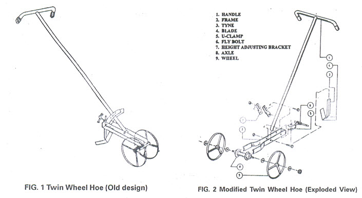
3.2.1.1 Frame:
In earlier design this part used to be made of ISI section. This was replaced by ISF section to make the use of die possible for cutting and to reduce the length of welding.
3.2.1.2 Height Adjuster:
This component in old design was made of ISF section and given curvature by manual hammering and then welded to the frame, thus consuming lot of labour. This was replaced by detachable height adjuster, which is lighter and easy to fabricate with the help of jigs and dies.
3.2.1.3 Axle:
The earlier design had fabricated axle, which required operation on lathe. This was replaced by standard bicycle axle thus completely eliminating the time devoted on turning.
3.2.1.4 Blade:
The old design had blade made of two uniform pieces welded together at centre to form one piece. It was observed that the think cutting edge of the blade used to get damaged during welding. The design improvement in this case was replacement of two pieces by single piece thus eliminating the welding and the probability of damage to cutting edge.
3.2.1.5 Wheel bush:
Wheel bush was used to fabricate from 20 dia. round bar, which required turning to make inner diameter of 10 mm and parting on lathe. Operation on lathe was completely eliminated by replacing this bush by BSW hexagonal nut of equivalent size.
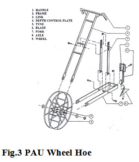
3.2.2 PAU Wheel Hoe Weeders (Fig.3)
The only component redesigned in PAU wheel hoe was handle frame support. This component in the original design was made of tube section of 18 dia. The tube section required cutting on lathe/hack saw and subsequently forging of ends to weld the same properly in position. During welding the tube section requires precise current setting and skill in welding to avoid formation of holes. To overcome this problem, the tube section was replaced by flat section. This flat section was cut on shearing cum punching machine in triangular shape and welded in position without any difficulty. The time required in fabrication and welding was reduced thus.
 3.3 Identification of Production Process for different components:
The production process for each component was identified considering the facilities generally available with the small scale industries. The details of production process of each component are as detailed below:
3.3.1 Twin Wheel Hoe
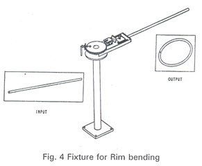
3.3.1.1 Wheel:
A fixture (fig.4) was designed to bend the round bar to form a wheel rim. Another fixture was designed to weld wheel rim, bush and spokes to form wheel sub-assembly.
3.3.1.2 Axle:
The earlier design was provided with an axle fabricated by turning 20 round bars. This was replaced by standard bicycle axle, thus completely eliminating the time devoted on fabrication of axle which was 18 man-min.
3.3.1.3 Frame:
Frame in the earlier design was made of angle section which was used to cut on power hack saw. This was replaced by flat section which was cut on fly press with the help of die and again bent on fly press with the help of another die. Thus the time required in fabrication was reduced to 35 man-min in comparison to 26 man-min with the earlier method. For welding the fork arm, fork base and axle together a fixture was designed.
3.3.1.4 Blade:
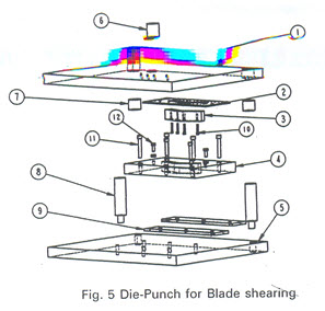
In this case the material spring steel was replaced by mild steel. Spring steel blade was made into two pieces and welded to form one piece. This also required annealing, machining, hardening and tempering. The mild steel blade was made in one piece, machined and carburized for giving hardness. With this, identification the quality of the blade improved and also the time required in fabrication was reduced to 12 man-min from 16 man-min required for spring steel blade. A die-punch (Fig.5) was designed to make one piece blade from mild steel sheet. A fixture was also designed for bevelling edges of blade on shaping machine.
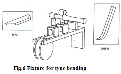
3.3.1.5 Tyne :
A fixture (Fig.6) was designed and developed to bend tyne in a definite curvature. The tyne is required to be heated before subjecting to bending on the fixture.
3.3.1.6 Height Adjuster:
For height adjuster also a die for bending and a jig for drilling 4 holes were designed. In the earlier production process these adjusters were given curvature by manual hammering and welded to the frame permanently. In the existing method, the height adjusters were made detachable and the production process involved the use of jigs for drilling and dies for bending. In this case also the labour requirement reduced to 7 man-min from 14 man-min.
3.3.2 PAU Wheel Hoe
3.3.2.1 Wheel :
Fixture (Fig.4) for bending rim of twin wheel hoe was incorporated with provided for adjusting the same to the size of PAU weeder rim. An extra disc with 380 mm diameter was designed which can be mounted on the same fixture to make it suitable for PAU wheel rim.
3.3.2.2 Handle Frame:
A die forging the ends of handle frame was designed. Another die for making U-notch on the forged ends with the help of fly press was also designed.
3.3.2.3 Fork :
U-notch on the ends of form a rim was made by using a die. A fixture for welding form arms and form base was designed.
3.3.2.4 Tyne :
A fixture for bending tyne in particular radius was designed. The tyne need be heated before subjecting to bending on fixture.
3.3.2.5 Depth control plate :
Depth control plate was drilled with 8 nos. of 80 holes on a jig. A jig containing buttons for clearance for smooth removal of cut material had been designed.
3.3.2.6 Blade :
Bending of blade was carried out on press brake. A fixture was designed to bevel edges of blade on shaper. A fixture was also designed for welding blade, tyne and depth control plate together.
3.4 Production Process of weeders :
Table 1shows the detailed production process for twin wheel hoe weeder. Material used for each component and the time taken in fabrication of each is also detailed in the table. The production process also contains the sequences of operation followed and the machine used for each component.
Table – 1 : Production Process and time for fabrication of Twin Wheel Hoe
|
Component & Process |
Material and Machine |
Time (Man-Min) |
|
A. Wheel Sub-Assembly |
|
|
|
1 Rim |
ISRO 100 |
|
|
a. Straightening |
Straightening die |
12.00 |
|
b. Shearing |
Shearing cum punching |
0.40 |
|
c. Straightening |
Hammering |
4.00 |
|
d. Bending |
Die |
3.00 |
|
e. Welding |
Arc |
2.00 |
|
f. Final straightening |
Forging hammer |
0.60 |
|
2. Spokes |
ISRO 10 0/ |
|
|
a. Straightening |
Straightening die |
5.00 |
|
b.Shearing |
Shearing cum punching |
2.00 |
|
c.Straightening |
Hammering |
3.00 |
|
3. Bush |
Nut 7/16’’ |
|
|
a. Turning |
- |
|
|
b. Welding(Rim, spoke & Bush)Fixture |
|
10.00 |
|
4. Axle |
Standard Bicycle Axle |
|
|
a. Step turning |
- |
- |
|
b. Parting |
- |
- |
|
c. Drilling |
- |
- |
|
Subtotal |
|
42 |
|
Component & Process |
Material and Machine |
Time(man-Min) |
|
B. Handle Sub-Assembly |
|
|
|
1.Handle |
IST 25 0/ |
|
|
a. Turning |
Lathe |
0.80 |
|
b. Bending |
Pipe bending |
5.00 |
|
2.Handle Frame |
Its 25 0/ |
|
|
a. Turning |
Lathe |
1.00 |
|
b. Drilling |
Drill |
2.00 |
|
c. Welding (Handle & Handle Frame) |
Fixture |
6.00 |
|
Sub-Total |
|
15 |
|
C. Frame Sub-Assembly |
|
|
|
1.Frame Arm |
ISF 25 X 5 |
|
|
a. Straightening |
Hammering |
|
|
b. Shearing |
Shearing cum punching |
|
|
c. Straightening |
Hammering |
|
|
d. Shearing |
Fly press |
|
|
E. Drilling |
Drill |
|
|
f. Bending |
Fly Press |
|
|
2. Fork Base |
ISF 25 X 5 |
|
|
a. Straightening |
Hammering |
0.50 |
|
b. Shearing |
Shearing cum punching |
0.40 |
|
c. Straightening |
Hammering |
0.50 |
|
d. Welding (form arm & base)Arc |
|
6.00 |
|
4.Height Adjuster |
ISF 30 X 3 |
|
|
a. Straightening |
Hammering |
1.00 |
|
b. Shearing |
Shearing cum punching |
0.50 |
|
c. Straightening |
Hammering |
1.00 |
|
d. Drilling |
Drill(Jig) |
3.00 |
|
e. Bending |
Fly Press |
2.00 |
|
f. Welding fork & height adjuster |
-- |
-- |
|
Sub-Total |
-- |
24 |
|
D. Blade Sub-Assembly |
|
|
|
1.Tyne |
ISSQ 16 |
|
|
a. Shearing |
Power Hack Saw |
3.00 |
|
b. Bending |
Hammering |
1.50 |
|
2. Blade |
MS Sheet 3 mm |
|
|
a. Annealing |
-- |
-- |
|
b. Shearing |
Power Press |
1.00 |
|
c. Shaping |
Shaper |
5.00 |
|
d. Welding |
-- |
-- |
|
d. Bending |
Press Brake |
0.50 |
|
f. Heat treatment |
Carburizing |
3.50 |
|
g. Welding (Blade & Tyne) |
Arc |
2.00 |
|
E.U-Clamp Sub –Assembly |
|
|
|
1.U-Clamp |
ISF 30 X 5 |
|
|
a. straightening |
Hammering |
1.00 |
|
b. Shearing |
Shearing cum punching |
0.50 |
|
c. Straightening |
Hammering |
0.50 |
|
d. Slot cutting |
Power Press |
0.50 |
|
e. Drilling |
Drill |
1.00 |
|
f. Bending |
Die |
1.00 |
|
g. Nut welding |
Arc |
2.00 |
|
2.Bush |
IST 14 0/ |
|
|
a. Parting |
Lathe |
1.00 |
|
3.Scarper |
ISRO 12 0/ |
|
|
c.Straightening |
Hammering |
0.50 |
|
b. Shearing |
Shearing cum punching |
0.40 |
|
c.Straightening |
Hammering |
0.20 |
|
d. Forging |
Hammering |
2.00 |
|
e. Welding (bolt & bush) |
Arc |
1.00 |
|
Sub-Total |
Say |
28 |
|
F. Derusting & chipping |
Manual |
3.00 |
|
G. Primer Coating |
Dipping |
4.00 |
|
H. Paint Coating |
Dipping |
5.00 |
|
I. Assembling |
Manual |
5.00 |
|
Grand Total |
|
129 |
Fabrication of wheel hoe weeder with the modified method (with tooling aids) took 2.15 man hour for fabricating one unit in comparison to 3.32 man-h with the existing method (without tooling aids).Thus the saving in labour in case of modified method was 1.17 man-h i.e.35
As far as saving in material is concerned, the twin weeder fabricated with modified method weighed 1.5 kg less. The saving in material has been achieved by replacing heavier sections with lighter section. The replacement has been yield not only material saving and reduction in weight but the ease in fabrication as well. Time consuming operations like manual bending of height adjusters, fabrication of axle on lathe etc. have been completely eliminated.
3.5 Project Profile
1. Product : Twin Wheel Hoe & PAE Wheel Hoe
It is proposed to manufacture two different designs of wheel hoe weeds. Twin wheel hoe and PAU wheel hoe. Wheel hoe weeders has been in great demand for weeding operation, Wheel hoe weeders has got advantage over traditional khurphi in respect of labour, time and drudgery in weeding operation.
2. Production target : Twin Wheel Hoe - 2000 units per annum
PAU Wheel Hoe - 1500 units per annum
The workshop will have facilities to fabricate 2000 units of Twin Wheel hoe and 1500 units of PAU wheel hoe weeders in a year.
3. Land & Building : Constructed shed of 1500 sq. ft. and open area of 1500 sq.ft.
The shed is proposed to be taken on rent @Rs.3000/- per month
4. Machinery requirement:
|
SI. No. Machine & Description
|
Quantity |
Approx. cost |
|
1. Spanner Set |
4 |
1000/- |
|
2. Hand tools kit |
2 |
1000/- |
|
3. Anvil |
2 |
5000/- |
|
4. Arc welding et, 600 amp |
1 |
25000/- |
|
5. Pillar drill, 13 mm |
1 |
20000/- |
|
6. Fly press, 20 t |
1 |
20000/- |
|
7. Power hack saw, 12’’ blade |
1 |
10000/- |
|
8. Abrasive cut off machine |
1 |
10000/- |
|
9. Mechanical pipe bending machine |
1 |
5000/- |
|
10. Tooling |
1 set |
15000/- |
TOTAL 112000/-
In finalizing the machinery requirement care has been taken to keep the expenditure on machinery as low as possible. A new entrepreneur can start the workshop with minimum machinery as a detailed in the table above. Owing a lathe will be too expensive, as a such as abrasive cut of machine has been proposed which can be used for cutting various sections like angle, rod,flat,pipe etc.Similarly Owing a power press will also be not economical, considering the size of sections involved in farbrication.It will be underutilized always. A fly press will be enough to meet out the fabrication requirement. For the components involving press work and heat treatment etc. Like in case of fabrication of blade, it is proposed that the same can be got done outside on contract basis.
5. Raw Material requirement:
This has been calculated from the manufacturing drawings of both the weeders.
|
S.NO. |
MATERIAL |
Qty |
Unit Weight |
Qty by weight (kg) |
Rate (Rs./kg) |
Approx. Cost |
|
1. |
ISRO 12 |
200m |
0.89 |
178 |
17 |
3000 |
|
2. |
ISRO 10 |
7500m |
0.62 |
4650 |
17 |
79000 |
|
3. |
ISRO 6 |
3225m |
0.22 |
710 |
17 |
120000 |
|
4. |
IST 40 |
32 m |
- |
- |
90 per m |
3000 |
|
5. |
IST 25 |
5400 m |
- |
- |
20 per m |
108000 |
|
6. |
IST 18 |
3450 m |
- |
- |
16 per m |
55200 |
|
7. |
IST 14 , 2 thick |
45 m |
- |
- |
30 per m |
1400 |
|
8. |
ISSQ 16 |
38 m |
2.01 |
765 |
17 |
13000 |
|
9. |
ISSQ 12 |
480 m |
1.13 |
542 |
17 |
9200 |
|
10. |
ISF 65 X 5 |
102 m |
2.5 |
255 |
17 |
4300 |
|
11. |
ISF 30 X 5 |
260 m |
1.2 |
312 |
17 |
5300 |
|
12. |
ISF 30 X 3 |
420 m |
0.7 |
294 |
17 |
5000 |
|
13. |
ISF 25 X 5 |
2530m |
1.0 |
2530 |
17 |
43000 |
|
14. |
ISF 20 X10 |
1200 m |
1.6 |
1920 |
17 |
32600 |
|
15. |
MS Sheet 3mm |
36 sq.m |
24.70 |
890 |
22 |
19600 |
|
16. |
Standard axle |
3675 nos. |
- |
- |
20 |
15000 |
|
17. |
Nut bolts |
500 kg |
- |
- |
30 |
15000 |
|
|
Total (say) |
|
|
|
|
480000 |
Note The quantity includes 5 & 10 % allowance towards wastage on account of scrap/rejection for purchased & sheet metal parts.
6. Manpower:
|
S.No |
Description |
Man Days |
Rate (Rs/man-days) |
Amount |
|
1. |
Supervisor or Entrepreneur |
300 |
100/- |
30000/- |
|
2. |
Skilled technician |
600 |
100/- |
60000/- |
|
3. |
Unskilled worler |
600 |
70/- |
42000/- |
Total 132000/-
7. Miscellaneous expenditure (20% of rows material): Rs.96000/- (Say)
This also includes expenditure on contract services like press work, shaping work, heat treatment etc.
8. Total working capital (Monthly basis)
i. Rent of building : Rs.3000/-
ii. Cost of raw material : Rs.40000/-
iii. Overhead expenditure : Rs. 8000/-
iv. Salary : Rs.11000/-
Total : Rs. 62000/-
9. Essential working capital (for 3 months) : Rs. 186000/-
10. Total project cost
i. Cost of machinery : Rs.112000/-
ii. Essential working capital : Rs.186000/-
Total : Rs.298000/-
11. Production Cost
i. Annual Working Capital : Rs.744000/-
ii. Depreciation : Rs. 11200/-
iii. Interest on capital from bank @ 14% : Rs. 31300/-
(75% of project cost)
Total : Rs.786500/-
12. Profit from unit :
i. Scale proceed:
Twin wheel hoe 2000 units @ Rs.250 /- each : Rs . 5,00,000 /
PAU wheel hoe 1500 units @ Rs. 300 / - each : Rs . 4,50,000
ii. Profit ( scale proceed –production cost ) : Rs.1,63,500/-
iii. Monthly profit (Say) : Rs .13,625/-
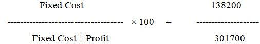
13. Break Even Point :
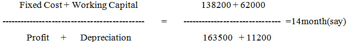
14. Pay back period :
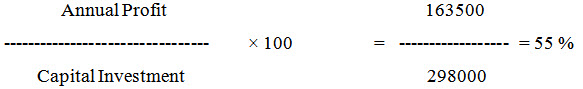
15. Return on investment :
3.6 Suggestion
Entrepreneur should install the minimum machinery required and for machine specific jobs like press work , heat treatment etc.., he should get the work done from outside on contract basis .
Reference:
Uday R.Badegaonkar, Case study of Manufacturing of Weeders , Scientist (SG), Central Institute of Agricultural Engineer, Bhopal
Last modified: Friday, 28 March 2014, 5:27 AM