Site pages
Current course
Participants
General
MODULE 1. Introduction to production of agricultur...
MODULE 2. Advance in material for tractor and agri...
MODULE 3. Advanced manufacturing techniques
MODULE 4. Heat treatment of steel
MODULE 5. Industrial lay out planning and quality ...
MODULE 6. Economics of process
MODULE 7. Techno economic feasibility of project r...
MODULE 8. Servo motors, drives and controllers
MODULE 9. CNC controllers for machine tools
MODULE 10. CNC programming
MODULE 11. Assembly and plant automation storage a...
LESSON 23. CRITICAL COMPONENTS AND THEIR SELECTION
4.1 What is a component?
When a machine, for instance a power thresher, is exploded, it is resolved into a number of sub-assemblies, and then each sub-assembly into a number of parts. A is the last exploded unit which may perform independent function in a machine. A part or a group of parts together in a machine is addressed as a component. As for instance, the gear box in a reaper comprises of number of parts and hence it may be called a component . However, there exists a dichotomy between a part and a component and these two terms are often interchangeably used or used at times together as component part. Thus a part is a subset of a component. In a part, the various portions labelled with dimensions are called links.
4.1.1 Meaning of critical
The term “critical” is related to decision-making or crisis or turning point.
4.1.2 What is a critical component?
The component responsible for creating a crisis by its wrong-working or faltering is called critical. A component may be critical in a machine, and so also a part. Thus, a critical component or say a critical part in a machine will cause the machine to dysfunction if the same is not properly designed, manufactured or repaired/maintained or selected. But most critical components or parts are available in market in ready-to-use form, the selection of which is, therefore, very important for the particular machine and conditions of operation. As for instance, the examples of these are bearings & housings, pulleys & belt, gears etc. Besides, the same critical components or parts may be fabricated also. These are, for example, lynch pins of tractor mounted implements. Thus, most of the critical parts and components are available in the market as standard material and no separate effort is, there-fore, required to design and fabricate them. One is, therefore, required to select the right one. A glimpse of such parts is presented in next section.
4.2. Standard Parts
4.2.1 Common bought-out parts
Almost all types of standard parts used commonly in common machines are also used in agricultural equipment. A classification of the standard bought-out parts is presented in Fig.1. The criteria of selection of individual part are dealt in the subsequent sections through a few example cases.
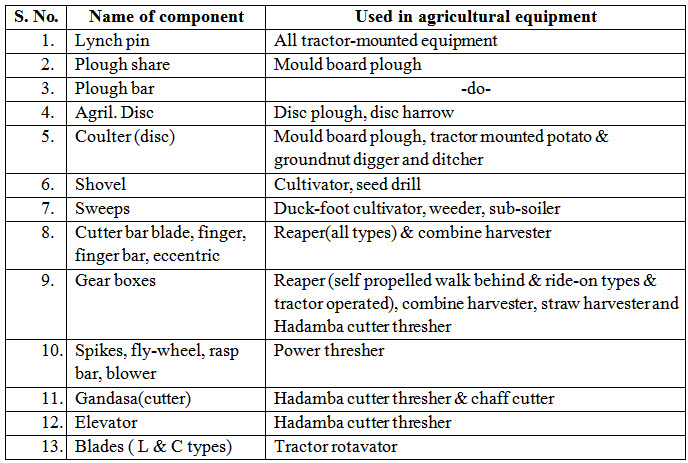
4.2.2 Specific bought-out parts
Some parts used in agricultural equipment are not normally used in other machines but are specific to one more agricultural equipment. These have been in exhaustively listed in Table 1. Some industries fabricate of them in their own units along with other components of implements and therefore they may not conform to standard dimensions.
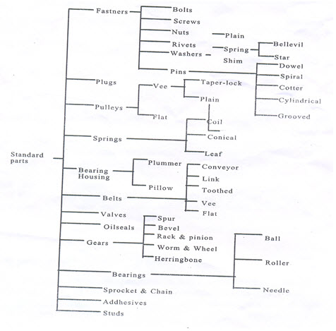 Figure : 1
Table 1 . Bought-out / fabricated parts specific to agrl. Equipment
(This list is illustrative only.)
4.3.Selection criteria
In this lecture note, only a few parts have been selectively covered to explain criteria of selection. One may need to look into the following general criteria in selecting a critical component part.
i. Material
ii. Intricacy of design
iii. Quality of manufacturing
iv. Metallurgy, longevity, wearing, etc.
v. Space limitations
vi. Load and power
vii. Cost
4.4. Material:
Material finds an important place in design of a critical component part of agriculture equipment. The performance and reliability of a component depends largely on the type and quality of material used in the parts and process of manufacturing. The quality of material refers to the following and is desirable for the design engineer to tread a course between functional quality requirement on one hand and cost consideration on the other although quality may over ride cost in some rare cases.
i. Strength
ii. Toughness
iii. resistance to wear and corrosion
iv. good scour (quality of material to allow easy flow)
v. lightness of weight, and
vi. low initial cost and subsequent upkeep requirement
In the present days, design is no longer and the consideration of time factor these days has necessitated the knowledge of the right materials and their use right from the beginning. It is also important to update one’s knowledge of new material being introduced every day in order to maximize on their use.
4.5. Specific cases
Here we deal with a few case examples to introduce the ideal of selection of critical components.
4.5.1 Bearing
For a bearing it is important to know in the first instant the nature of loads the bearing is to carry. According to the type of loading namely axial, radial or mixed, the bearings have been classified as shown in Fig 2.
Selection of bearing
Bearing are classified in the manner as shown in Fig 2. The types of bearing and their nature of loading like radial, axial and mixed besides speed of operation have been give in this section. Moreover, it is also important to know the relationship between the load and life of bearing. The relationship is established by Eqs.1 & 2 and life calculation chart. Similarly the class of machines and their useful lives are presented in Table 2 for deciding the types of bearing to be used.
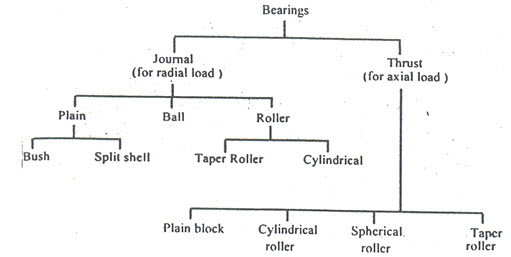
Fig.1. classification of bearings according to load
Revised life equations established by ISO 281 are:
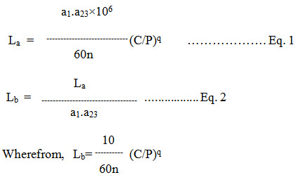
Where,
La = Adjusting rating life, h
Lb = Basic operating life, h
a1 = life adjustment factor for reliability
a23 = Combined life adjustment factor for material and operating condition
n = rpm
C = Basic Dynamic Load Rating, Newton
P = Equivalent Dynamic Bearing Load, Newton
q= exponent for life equation = 3 for ball bearing and 10/3 for roller bearing, and
C/P = Load ratio
Rise in operating temperature affects the hardness and bearing material. This affects C by the factor of temperature, f, as C.f.
Bearing temperature,0C
Bearing temperature,0C 150 200 250 300
Temperature factor, f 1.0 0.9 0.75 0.6
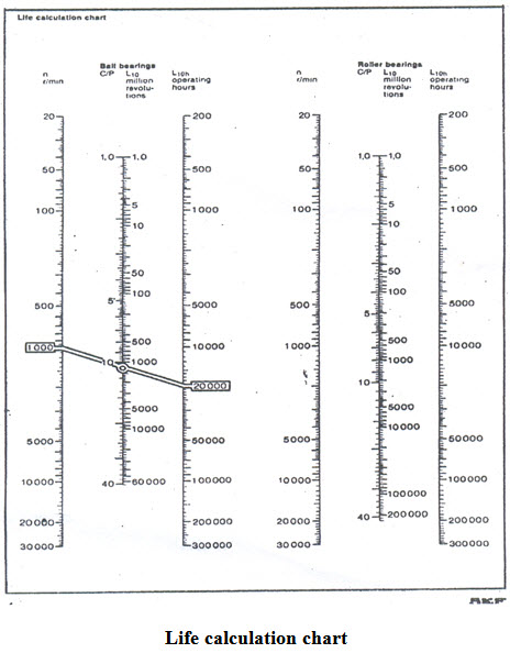
Table2.Class of machines and their basic operating lives
|
S.NO |
Class of machine |
Basic operating life, h |
|
1 |
Domestic & Agril.Machine |
300-3,000 |
|
2 |
Electric hand tools & other intermitted machines |
3,000-8,000 |
|
3 |
High operational reliability for short periods |
8,000-12,000 |
|
4 |
Machine used 8h/d but not fully utilized |
10,000-25,000 |
|
5 |
Machines used 8h/d and fully utilized |
20,000-30,000 |
|
6 |
Machines used 24h/d like pumps, compressors etc. |
40,000-50,000 |
|
7 |
Rotary furnace , water works |
60,000-1,00,000 |
|
8 |
Large electric machinery, pulp& paper making machinery |
>1,00,000 |
Similarly the values of a, are also given by Table 3.
Reliability means the probability that a bearing will or exceed a specified life
Table 3. Reliability * versus a1
|
S NO. |
Reliability,% |
A |
S NO. |
Reliability,% |
a |
S NO. |
Reliability,% |
a |
|
1 |
90 |
1 |
3 |
96 |
0.53 |
5 |
98 |
0.33 |
|
2 |
95 |
0.62 |
4 |
97 |
0.44 |
6 |
99 |
0.21 |
a: The value of a is obtained in the following manner.
*Reliability means the probability that a bearing will attain or exceed a specified life.
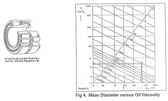
For a selected roller bearing cylindrical bore of 18?5=90mm,22318CC/W33, W33 Feature is peripheral groove and 3 lubrication holes in the outer ring, value are:d =inside bore = 90 mm;
іD₀=outside diameter=190mm;
Thus d =average diameter =(90+190)/2=140mm.From Fig 4 corresponding to
dm=140mm,v =Satisfactory oil viscosity =21 mm²аа/s at 500 rpm.
Hence ,k=v/v=35₍as given₎/21=1.61 and from Fig 5,fork=1.67,a₂₃=1.4
Thus,Lа=a₁.a₂₃‘10⁶/60n(C/P)q=0.33(1.4)’10⁶/60’500(4,77,000/50,000)10/3=28358h
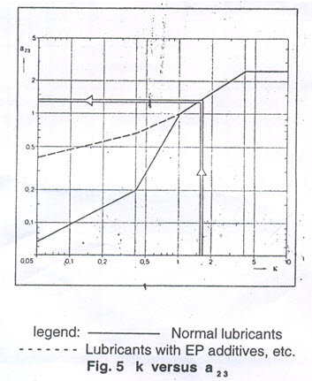
Lengend:—Normal lubricants
--..Lubricants WithEp additives , etc.
4.5.2 Gear selection
In agricultural equipment, two types of gears are most common. These are spur and bevel gears. In these sections, selections of spur gear are presented.
a)Modules of gear
module is the inverse of number of teeth in one unit diametric pitch of gear. Two spur gears will match only when they match in their modules . hence, module is an important guiding factor of matching gear pair.
According to recommendations in IS:2535-1969,the18 modules of gears are:
1 2 4 8 16 32
1.25 2.5 5 10 20 40
1.5 3 6 12 25 50
The definitions of some terms are:
i. Z=NO .Of teeth of a gear = Pitch circle Diameters / module=dₒ/m
ii. Diametral Pitch ,DP =No. of teeth /No. of inches in pitch circle diameter=Z/dₒ=1/m
iii. Circular pitch , Cp =Distance of consecutive teeth measured along pitch circle =π .dₒ/Z
Thus , we have the relation, DP ×CP=π
Or, m=dₒ/Z=CP/π= Sum of addenda of circle Diameters , da , of the two gears
Z1+Z2
= 2×Centre distance of two gears
Sum of teeth of the gears
The 21 typical gears are of teeth
20 30 40 50 60 70 80 90 100 120 127
25 35 45 55 65 75 85 95 110 125
5 (c) Selections of V- belt & pulley
V-belts are mostly used in powera
Commonly used belts it is necessary to know how to select a V-belt .
Selections of a V - belt means
i. Selection of the section of pulley & belt
ii. No. of belts (and belt design)
iii. Belt tensioning and
iv. Care and conditions of use
However ,V-belts should satisfy quality - standards in BS-3790 or DIN-2215 or IS-2494 (for V-belt in power rating ) & IS : 3142 (for cast iron pulley sections).
1. Selection of section of pulley and belt
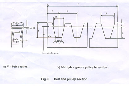
V-belts and pulley come in standard sections of A,B,C,D and E. And some special sections among five are also manufactured in belts by some manufacturers. The sectional geometries of the belts and pulleys and are presented in Fig 6 while the dimensions in Table 4
|
section |
Belt attributes |
Pulley attributes |
||||||||||
|
|
W mm |
Ip mm |
H mm |
Belt speed m/s |
Belt wt.kg/m |
B mm |
t mm |
e mm |
f mm |
? mm |
dp mm |
g mm |
|
W for belt width; ᴵp for belt pitch width; H for belt height; b for addendum; t for groove height; e for pitch of groove end distance; ? for groove angle; dp for pulley diameter min; g for groove top width |
||||||||||||
|
A 13 11 8 30 0.112 3.3 12 15±0.3 9 to 0.4 |
34
|
75 to 124 |
13
|
|||||||||
|
38 |
³125 |
13.3 |
||||||||||
|
B 17 14 11 30 0.193 4.2 15 19±0.4 11.5to 14.5 |
34
|
125 to199
|
16.6
|
|||||||||
|
38 |
³200 |
16.9 |
||||||||||
|
C 22 19 14 30 0.33 5.7 20 25±0.5 16 to 19 |
26
|
200to 299 |
22.7
|
|||||||||
|
28 |
³300 |
22.9 |
||||||||||
|
D 32 27 19 30 0.675 8.1 28 37±0.6 23 to 27 |
36
|
355to 499 |
32.3
|
|||||||||
|
38 |
³500 |
32.6 |
||||||||||
|
E 38 32 23 30 1.030 9.6 33 44.5±0.7 28 to 33 |
36
|
500to 629 |
38.2
|
|||||||||
|
38 |
³630 |
38.6 |
||||||||||
The selection of pulley &belt both in any one category of A,B,C,D,E& any special category will depend on the factors like
Power to be transmitted
Speed at which to be transmitted, and
The working conditions.
Of course, the former two are more important because power=torque, T’ angular motion ?.the angular rotation can be in terms of rpm(rotation of pulley per minute). For selection of the belt cross.
Fig 7 may be referred. From this figure, for a 5 kW of power transmission, we can select C-section V-belt to 175 rpm(on the ordinate)or B-section belt for rpm between 175 to 775 rpm(A&B on the ordinate) or A-section belt for rpm between 77 to 5,000rpm(p & q on the ordinate). And the further calculation of number of belts will decide whether the pulley will be of single groove.
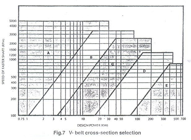
Once section is graphically selected from fig. 7, the power which one belt of the selected section can transmit can be also selected from the power versus rpm given in Table 5 for given (standard) pulley diameters (pitch circle). Normally, the prime-movers are electrical motors; hence, the rpm are 720, 960, 1440 or 2880.
Table 5 Power transmission of belt
|
Pulley size in mm |
Pulley section |
Capacity to transmit power ,Kw, at Pulley rpm |
||||||
|
720 |
960 |
1440 |
2880 |
|||||
|
75 |
A |
0.62 |
0.76 |
0.98 |
1.36 |
|||
|
80 |
A |
0.75 |
0.92 |
1.21 |
1.75 |
|||
|
90 |
A |
0.94 |
1.17 |
1.57 |
2.38 |
|||
|
100 |
A |
1.11 |
1.39 |
1.88 |
2.94 |
|||
|
112 |
A |
1.32 |
1.67 |
2.28 |
3057 |
|||
|
125 |
A |
1.54 |
1.95 |
2.68 |
4.26 |
|||
|
125 |
B |
2.00 |
2.46 |
3.23 |
4.39 |
|||
|
132 |
B |
2.25 |
2.79 |
3.70 |
5.08 |
|||
|
140 |
B |
2.41 |
3.01 |
4.00 |
5.58 |
|||
|
160 |
B |
3.03 |
3.79 |
5.08 |
7.10 |
|||
|
180 |
B |
3.57 |
4.51 |
6.04 |
8.31 |
|||
|
200 |
B |
4.21 |
5.29 |
7.12 |
- |
|||
|
200 |
C |
5.50 |
6.78 |
8.75 |
- |
|||
|
212 |
C |
6.16 |
7.61 |
9.86 |
- |
|||
|
224 |
C |
6.63 |
8.21 |
10.65 |
- |
|||
|
250 |
C |
8.00 |
9.92 |
12.84 |
- |
|||
|
280 |
C |
9.28 |
11.49 |
14.79 |
- |
|||
|
355 |
C |
12.89 |
15.82 |
19.7 |
- |
|||
|
355 |
D |
20.52 |
24.51 |
24.58 |
- |
|||
|
375 |
D |
22.52 |
26.88 |
- |
- |
|||
|
400 |
D |
25.00 |
29.70 |
- |
- |
|||
|
450 |
D |
29.76 |
35.09 |
- |
- |
|||
|
500 |
D |
34.25 |
39.89 |
- |
- |
|||
|
560 |
D |
39.33 |
44.84 |
- |
- |
|||
|
450 |
E |
27.20 |
30.68 |
- |
- |
|||
|
500 |
E |
32.13 |
35.34 |
- |
- |
|||
|
600 |
E |
41.60 |
- |
- |
- |
|||
|
630 |
E |
44.25 |
- |
- |
- |
|||
|
710 |
E |
50.40 |
- |
- |
- |
|||
|
750 |
E |
52.97 |
- |
- |
- |
|||
Number of belts
The procedure to calculate the number of belts once the belt & pulley section is determined previously from fig 7 can be explained in the following steps with the of an example of driving a centrifugal at 2400 rrpm being run 18 hours a day by a 22 kW, 2880 rpm, 3-phase electrical (A.C) motor at 600mm centre distance. The steps involved to calculate the number of belts are:
|
SI NO |
Step |
Calculation |
||
|
1 |
Determine the belt & pulley section from fig 7 corresponding to p=22kW of power and n=2880 rpm |
B section of belt & pulley for n=2880 rpm & p=22kW |
||
|
2 |
Calculate speed ratio, r,from r=N1/N2=Dp/dp |
R=2880/2400=1.2 |
||
|
3 |
Select the motor pulley from amongst the standard preperred diameters (PCD) of 85,90,100,106,112,118,140,150,160,170,180,190,200, 224,212,236,250,265,280,315,355,375,400,425,450,500, 530,560,600mm and some non-preferred ones of 75,80,125,132,670,710,750,800,850,900,950 &1000. |
We select Dp=smaller pulley for motor =150 mm
|
||
|
4 |
Compute C2=service factor from Table 6 |
C2=1.2 from table 6 against light-duty,star-delta start & over 16 hours of works/day |
||
|
5 |
Pitch diameter of slower pulley,Dp=r xdp |
Dp=1.2 x 150 =180 mm |
||
|
6 |
Check drive center distance C, suitable if 0.7 (Dp+dp)<2.0 (Dp+dp) |
C=600mm as chosen is OK. |
||
|
7 |
Select belt length (pitch) from Lp=2C+1.57(Dp+dp)+(Dp-dp)2 / 4C |
Lp=2x600+1.57(180+150)=180-150)2 / 4x600)=1718mm; and from Table 7,the nearest standard length isn1720 mm=L |
||
|
8 |
Cc,Ca C=C+(L-Lp)/2 if l>lp Or C=C-(L-Lp) /2 if L<Lp K=(L- /2 (Dp+dp)) /4 Ca=K+(K2-(Dp-dp)2 /8)) |
Cc=600 +(1720-1718)/2=601 mm and Ca= 600.76mm |
||
|
9 |
For arc of contact correction factor, C1,take the value of C1 from Table 8 corresponding to (Dp-dp)/c |
(180-150)/600=0.05 C1 =0.99 Corresponding to .05 from Table 8 |
|
|
|
10 |
For correction factor, C3,of belt length, choose C3 from Table 9 corresponding to L |
C3 =0.94 from Corresponding to L=1720mm
|
|
|
|
11 |
Power rating pern belt, Pn Pn is taken from Table 10 corresponding to r, n & dp |
Pn = 5.55+0.50=6.05 kW for r=1.2; n=2880 rpm and dp=150mm from Table 10 |
|
|
|
12 |
No. Of belts,Z Z=(pxC2)/(pnxC2xC3) |
Z=(22x1.2)/6.05x0.99x0.94)=4.69 -5(taking next whole number) |
|
|
Thus 5 units of B 66/1760 belts will be required to transmit 22kW power.
3. Belt tensioning
Proper belt tensioning would not allow slip of belt on the pulley under maximum load condition. The procedure to ensure proper belt tensioning is as follows:
Step1. Apply the recommended load for the belt section and calculate deflation of belt, Ea, under the recommended load by the relation Ea=(ExC)/100
Where, E=Deflation/ 100mm of centre-to-centre distance.Take this value from
Table11
C=Centre-to-centre distance,mm;
The load is applied at the centre of belt span perpendicularly.
Step2. Adjust the drive until until the calculated deflation ‘Ea’ is obtained.
Step 3. In case of belt under long-time use,Ea increases to 1.3Ea for which retensioning is required.
Table 6 Service factor, C2, for belt drives
|
Class of duty |
Type of driven machine |
C2 |
|||||
|
Type of prime mover |
|||||||
|
|
|
SOFT START |
HEAVY START |
||||
|
PER DAY DUTY HOURS |
PER DAY DUTY HOURS |
||||||
|
<10 |
10 TO 20 |
<16 |
<10 |
10 TO 16 |
>16 |
||
|
Light duty |
Agitators (uniform),blowers,exhausters & fans (<7.5 kW),centrifugal compressors, pumps,belt conveyors (uniform) |
1.1 |
1.1 |
1.2 |
1.1 |
1.2 |
1.3 |
|
Medium of duty |
Agitators,mixers (Variable), blowers,exhausters,fans (>7.5 kW),(Noncentrifugal),rotary compressors, pumps,belt conveyors (non uniform),generator,exciter,power shaft,machines tools,wood working machines, screws (rotary) |
1.1 |
1.2 |
1.3 |
1.2 |
1.3 |
1.4 |
|
Heavy of duty |
Bucket elevator, compressors, pumps (reciprocating), conveyor (heavy duty),hoists,mills,pulverisers, punching machine,press, shear,screw (vibrating) |
1.2 |
1.3 |
1.4 |
1.4 |
1.5 |
1.6 |
|
Extra heavy duty |
Crushers (gyrator – jaw roll), mills (ball-rod-tube) |
1.3 |
1.4 |
1.5 |
1.5 |
1.6 |
1.8 |
Note: 1. Correct the tabulated C2 value by the factors.
Speed ratio of 1.00 To 1.24 multiply C2 by
-do- 1.25 to 1.74 multiply C2 by
-do- 1.75 to 2.49 multiply C2 by
-do- 2.50 to 3.49 multiply C2 by
-do- 3.50 and multiply C2 by
2.Soft start prime movers are AC are star-delta,shunt wound DC motor, IC engines with >-4 cyclinder, etc.
3. Heavy start prime movers are AC Direct-on-line start, DC series & compound wound, IC engines <4 cyclinders.
Table 7 V-belt sizes of polyester cord
|
S.No |
Section |
Length(inch / mm |
|
1 |
A |
A23/620,A24/645,…….,A76/1966(by Step of 1”/25mm),A78/2017,A80/2068,……,A84/2195(by step of 2”/50mm),A85/2195,A86/2220,……,A98/2525(by step of 1”/25mm);A100/2516,A102/2626,…..,A112/2880(by step of2”/50mm);A114/2932,A115/2982,A118/3033,A120/3064,A124/3186,A125/3211,A126/3236,A128/3267,A130/3338,A134/3440,A136/3490,A138/3541,A140/3696,A144/3793,A154/4430and A174/4456 |
|
2 |
B |
B26/703,…..,B120/3091 by step f 1”/25mm except bill/2775;B122/3142,B124/3194,B125/3218,B126/3244,B128/3294,B129/3320,B130/3345,B132/3396,B134/3447,B135/3472,B136/3498,B138/3548,B140/3599,B141/3624,B142/3624,B143/3675,B144/3701,B145/3726B146/3752,B148/3802,B150/3853….B156/4006 by step of 2”/50mmB157/4031,B158/4056,B160/4107,B162/4158,B164/4209,B165/4234,B166/4259,B168,4310,B169/4336,B170,4361,B173/4437,B175/4488,B178/4564,B180/4564,B185/4742,B186/4767,B190/4889,B192/4920,B195/4996,B196/4996,B197/5047,B200/5123,B204/5225,B205/5250,B210/5377,B215/5504,B218/5580,B220/5631,B225/5758,B238/6088,B240/6139,B275/7028,B278/7014 |
|
3 |
C |
C46/1224,C48/1275,C49/1301,C51/1351,C5/1453,C60/1580,C63/1656,C68/1783,C71/1859,C75/1961,C77/2012,C78/2037,C81/2113,C85/2215,C86/2280,C87/2266,C88/2291,C89/2317,C90/2342,C91/2367,C92/2393,C93/2418,C94/2444,C95/2469,C96/2494,C97/2590,C98/2545,C99/2571,C100/2596,C101/2621,…..C130/3358 by step of 1”/25mm except C121,C132/3409,C134/3459,C135/3485, C136/3510, C137/3561,C138/356,C139/3557,C140/3612,C142/3663,C144/3713,C145/3739,C146/3769,C18/3815,C150/3866,C152/3917,C153/3942,….C158/4069 by step 1”/25mm,C160/4120,C162/4171,C163/4196,C164/4222,C165/4247,C166/4272,C168/4223,C169/4349,C170/4374,C173/4450,C175/4501,C176/4526,C178/4577,C180/4628,C183/4704,C184/4730,C185/4755,C186/4780,C190/4882,C191/4907,C192/4933,C195/5009,C196/5034,C197/5060,C200/5136,C204/5237,C205/5263,C208/5339,C210/5390,C215/5517,C218/5592,C220/56444,C224/5748,C225/5771,C228/5847,C230/5898,C236/6050,C238/6101,C240/6152,C246/604,C248/6355,C250/6406,C252/6457,C255/6533,C258/6609,C260/6680,C262/6711,C268/6863,C270/6914,C277/7092,C280/7092,C280/7168,C284/7270,C285/7295,C290/7422,C298/7625,C300/7676,C305/7803,C308/7879,C328/8387,C330/8438,C340/8692,C358/9149,C360/9200 |
|
4 |
D |
D109/2848,D112/2924,D114/2975,D116/3025,D5118/3078,D120/3127,D122/3178,D124/3229,D128/330,D130/3381,D132/3432,D134/3483,D136/3533,D140/3635,D144/3736,D148/3838,D150/3880,D152/3940,D155/4016,D158/4092,D160/4143,D162/4194,D168/4346,D170/4397,D173/4473,D176/4550,D177/4575,D178/4600,D180/4651,D185/4778,D188/4854,D190/4905,D195/5032,D218/5616,D220/5667,D224/5769,D225/5794,D228/5540,D230/5921,D235/6058,D238/6124,D240/6175,D248/6378,D300/7699,D252/6480,D255/6556,D256/6581,D258/6632,D260/6683,D264/6784,D268/6889,D270/6937,D276/7089,D278/7140,D280/7191,D285/7318,D287/7369,D290/7445 298/7648,D300/7699,D314/8055,D320/8207,D328/8410,D330/8461,D336/8613,D340/8715,D358/9172,D360/9223,D368/9426,D380/9731,D390/9985,D394/10087,D396/10137,D398/10188,D408/10442,D418/10698 |
|
5 |
E |
E180/4664,E195/4689,E210/4815,E220/5065,E238/6137,E240/6188,E268/6899,E270/6950,E298/7661,E28/8423,E358/9185,E374/9592,E392/10049,E394/10100,E396/10150,E418/10709 |
Note:V-belt A 50/106 means an A section V-belt of 50” inside length & 1306 mm nominal pitch length.
Table 8 Correction factor, C1, of arc of contact
|
(DP-dP)/C |
?=Arc of Contact,degree |
C1 |
|
(DP-dp)/C |
?=Arc of Contact, degree |
C1 |
|
0.00 |
180 |
1.00 |
|
0.55 |
148 |
0.92 |
|
0.05 |
177 |
0.99 |
|
0.60 |
145 |
0.91 |
|
0.10 |
174 |
0.99 |
|
0.65 |
142 |
0.90 |
|
0.15 |
171 |
0.98 |
|
0.70 |
139 |
0.89 |
|
0.20 |
169 |
0.97 |
|
0.75 136 0.88 |
||
|
0.25 |
166 |
0.97 |
|
|||
|
0.30 |
163 |
0.96 |
|
0.80 |
133 |
0.87 |
|
0.35 |
160 |
0.95 |
|
0.85 |
130 |
0.86 |
|
0.40 |
157 |
0.94 |
|
0.90 |
127 |
0.85 |
|
0.45 |
154 |
0.93 |
|
0.95 |
123 |
0.83 |
|
0.50 |
151 |
0.93 |
|
1.00 |
120 |
0.82 |
Table 9 Length Correction Factor, C3
|
C3 |
Length for belt section, mm |
|
C3 |
Length for belt section, mm |
|||||||||
|
A |
B |
C |
D |
E |
|
|
A |
B |
C |
D |
E |
||
|
0.80 |
630 |
|
|
|
|
1.02 |
1940 |
2500 |
4060 |
|
|
||
|
0.81 |
|
930 |
|
|
|
1.03 |
|
|
|
6890 |
|
||
|
0.82 |
700 |
|
1560 |
2740 |
|
1.04 |
2050 |
2700 |
|
|
|
||
|
0.83 |
|
1000 |
|
|
|
1.05 |
2200 |
2850 |
4600 |
7620 |
|
||
|
0.84 |
790 |
|
1760 |
|
|
1.06 |
2300 |
|
|
|
|
||
|
0.85 |
|
1100 |
|
|
|
1.07 |
|
|
|
8410 |
|
||
|
0.86 |
890 |
|
|
3130 |
|
1.08 |
2480 |
3200 |
5380 |
|
|
||
|
0.87 |
|
1210 |
1950 |
3330 |
|
1.09 |
2570 |
|
|
9140 |
|
||
|
0.88 |
990 |
|
|
|
|
1.10 |
2700 |
3600 |
6100 |
|
|
||
|
0.89 |
|
|
|
|
|
1.11 |
|
|
|
|
|
||
|
0.90 |
1100 |
1370 |
2190 |
3730 |
|
1.12 |
2910 |
|
6860 |
10700 |
|
||
|
0.91 |
|
|
2340 |
|
|
1.13 |
3080 |
4060 |
|
|
|
||
|
0.92 |
|
1560 |
2490 |
4080 |
|
1.14 |
3290 |
|
7600 |
|
|
||
|
0.93 |
1250 |
|
|
|
|
1.15 |
|
4430 |
|
|
|
||
|
0.94 |
|
|
2720 |
4620 |
|
1.16 |
3540 |
4820 |
|
12200 |
|
||
|
0.95 |
|
1760 |
2800 |
|
|
1.17 |
|
|
|
|
|
||
|
0.96 |
1430 |
|
3080 |
|
|
1.18 |
|
5000 |
|
13700 |
|
||
|
0.97 |
|
1950 |
3310 |
5400 |
|
1.19 |
|
5370 |
|
|
|
||
|
0.98 |
1550 |
|
3520 |
|
|
1.20 |
|
6070 |
|
15200 |
|
||
|
0.99 |
1640 |
2180 |
|
|
|
1.21 |
|
|
9100 |
|
|
||
|
1.00 |
1750 |
2300 |
|
6100 |
|
1.24 |
|
|
10700 |
|
|
||
Table 10 Power rating of belt,Pn, for smaller pulley(or faster pulley) (θ =1800)
Section A belt
|
Speed of Faster Pulley,(rpm) |
Power in KW for pitch diameter, dp, Of smaller pulley, mm |
Add power in kw for r of |
||||||||||||
|
75
|
80 |
85 |
90 |
100 |
106 |
112 |
118 |
125 |
1.01 to 1.04 |
1.05 to 1.12 |
1.1 3to 1.24
|
1.25 to 1.51 |
1.52 & above |
|
|
720 |
0.53 |
0.60 |
0.68 |
0.75 |
0.90 |
0.99 |
1.07 |
0.16 |
1.26 |
0.01 |
0.03 |
0.05 |
0.07 |
0.09 |
|
960 |
0.66 |
0.76 |
0.86 |
0.95 |
1.14 |
1.25 |
1.37 |
1.49 |
1.61 |
0.01 |
0.04 |
0.06 |
0.09 |
0.12 |
|
1440 |
0.91 |
1.04 |
1.17 |
1.31 |
1.58 |
1.73 |
1.90 |
2.07 |
2.24 |
0.02 |
0.06 |
0.10 |
1.14 |
0.17 |
|
2880 |
1.42 |
1.67 |
1.91 |
2.14 |
2.59 |
2.76 |
3.11 |
3.36 |
3.63 |
0.04 |
0.12 |
0.20 |
0.27 |
0.35 |
Section B belt
|
rpm |
dp= 125 |
132 |
140 |
150 |
160 |
170 |
180 |
190 |
200 |
Speed ratio r is same |
||||
|
720 |
1.61 |
1.79 |
1.99 |
2.24 |
2.48 |
2.73 |
2.97 |
3.21 |
3.45 |
0.03 |
0.08 |
0.13 |
0.18 |
0.23 |
|
960 |
2.02 |
2.24 |
2.50 |
2.82 |
3.13 |
3.44 |
3.75 |
4.05 |
4.35 |
0.03 |
0.10 |
0.17 |
0.24 |
0.30 |
|
1440 |
2.72 |
3.03 |
3.39 |
3.8 |
4.26 |
4.68 |
5.09 |
5.50 |
5.90 |
0.05 |
0.15 |
0.25 |
0.36 |
0.46 |
|
2880 |
3.96 |
4.44 |
4.95 |
5.55 |
6.11 |
6.62 |
7.08 |
7.48 |
- |
0.10 |
0.30 |
0.50 |
0.71 |
0.91 |
Section C belt
|
rpm |
dp= 300 |
212 |
224 |
236 |
250 |
265 |
280 |
31 5 |
355 |
400 |
Speed ratio r is same |
||||
|
720 |
4.65 |
5.18 |
5.70 |
6.22 |
6.81 |
7.44 |
8.06 |
9.49 |
1105 |
1275 |
0.07 |
0.21 |
0.35 |
0.49 |
0.63 |
Section D belt
|
rpm |
dp = 355 |
375 |
400 |
425 |
450 |
475 |
500 |
530 |
560 |
600 |
Speed ratio r is same. |
||||
|
720 |
16.26 |
17.90 |
19.90 |
21.85 |
23.75 |
23.59 |
27.38 |
29.44 |
31.42 |
33.91 |
0.25 |
0.75 |
1.25 |
1.75 |
2.22 |
|
960 |
19.26 |
21.16 |
23.45 |
25.63 |
27.70 |
29.65 |
31.47 |
33.50 |
35.32 |
- |
0.33 |
1.00 |
1.67 |
2.33 |
3.00 |
|
1440 |
21.22 |
23.03 |
- |
- |
- |
- |
- |
- |
- |
- |
0.50 |
1.50 |
2.50 |
3.50 |
4.50 |
Section E belt
|
960 |
5.76 |
6.42 |
7.08 |
7.72 |
8.46 |
9.24 |
10.00 |
11.72 |
13.58 |
15.51 |
0.09 |
0.28 |
0.47 |
0.66 |
0.85 |
|
1440 |
7.49 |
8.36 |
9.21 |
10.03 |
10.95 |
11.91 |
12.82 |
14.76 |
16.67 |
- |
0.14 |
0.42 |
0.71 |
0.99 |
1.27 |
|
2800 |
8.05 |
|
|
|
|
|
|
|
|
|
0.27 |
0.82 |
1.37 |
1.92 |
2.47 |
|
rpm |
dp= 450 |
500 |
560 |
630 |
670 |
710 |
750 |
800 |
850 |
900 |
950 |
100 |
r= 1.01 to 1.04 |
r= 1.05 to 1.12 |
r= 1.27 to 1.57 |
>157 |
|
720 |
26.44 |
31.69 |
37.56 |
43.78 |
47.0 |
49.97 |
52.67 |
55.66 |
|
|
|
|
0.38 |
1.92 |
3.07 |
3.45 |
|
960 |
29.77 |
35.29 |
40.94 |
46.07 |
- |
- |
- |
|
|
|
|
|
0.52 |
2.60 |
4.16 |
4.68 |
Table 11 Deflection, of belt per 100mm of C
|
Belt section |
Applied Load on belt (Newton) |
dp=Small pulley diameter (mm) |
Deflection, E, per 100mm of C (mm) |
Belt section |
Applied Load on belt (Newton) |
dp=Small pulley diameter (mm) |
Deflection, E, per 100mm of C(mm) |
|
A |
25 |
75≤dp ≤100 100<dp≤1 32 dp>132 |
1.90
1.70
1.50 |
C |
100 |
200≤dp ≤265 265<dp ≤355 dp>355 |
2.30
2.10
2.00 |
|
B |
50 |
125≤dp 160≤ 160<dp ≤200 dp>200 |
2.30
2.10
1.90 |
D |
150 |
355≤dp ≤450 450<dp ≤670 dp>670 |
2.20
2.10
2.10 |
4. Conditions of use
1. Belts of a matched set of required number of correct length and section of the same make and not in a mix-up of new and old should be used.
2. Pulleys of uniform and smooth (Ra<6.3µ) free of oil & grease and monted close to the bearings should be used.
3. Pulleys higher than 30m/s of speed be dynamically balanced.
4. Belts should be stored at 13 to 25C in dry & light-free place & used in temperature medium not exceeding 60C.
5. Idler pulley to provide requisite tension should be flat placed externally on slack side and should be grooved, placed internally on the slack side of diameter at least equal to the smaller pulley such that a=contact angle same for both the puleys.
Critical Components and their Selection
Dr.H.S.Biswas
Head, Technology Transfer Division, Central Institute of Agricultural Engineering, Bhopal
PRODUCTION TECHNOLOGY OF AGRICULTURAL EQUIPMENT
SEPTEMBER 4-24.2002
Last modified: Friday, 28 March 2014, 6:42 AM