Site pages
Current course
Participants
General
MODULE 1. Introduction to production of agricultur...
MODULE 2. Advance in material for tractor and agri...
MODULE 3. Advanced manufacturing techniques
MODULE 4. Heat treatment of steel
MODULE 5. Industrial lay out planning and quality ...
MODULE 6. Economics of process
MODULE 7. Techno economic feasibility of project r...
MODULE 8. Servo motors, drives and controllers
MODULE 9. CNC controllers for machine tools
MODULE 10. CNC programming
MODULE 11. Assembly and plant automation storage a...
LESSON ?. CNC PROGRAMMING
1.1 Programming Fundamentals
Machining involves an important aspect of relative movement between cutting tool and workpiece. In machine tools this is accomplished by either moving the tool with respect to workpiece or vice versa. In order to define relative motion of two objects, reference directions are required to be defined. These reference directions depend on type of machine tool and are defined by considering an imaginary coordinate system on the machine tool. A program defining motion of tool / workpiece in this coordinate system is known as a part program. Lathe and Milling machines are taken for case study but other machine tools like CNC grinding; CNC Hobbing, CNC filament winding machine, etc. can also be dealt with in the same manner.
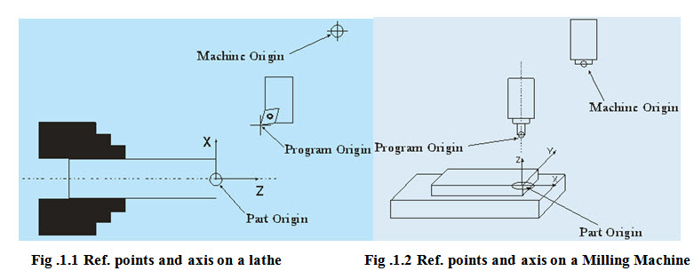
1.1.1 Reference Points
Part programming requires establishment of some reference points. Three reference points are either set by manufacturer or user.
a) Machine Origin
The machine origin is a fixed point set by the machine tool builder. Usually it cannot be changed. Any tool movement is measured from this point. The controller always remembers tool distance from the machine origin.
b) Program Origin
It is also called home position of the tool. Program origin is point from where the tool starts for its motion while executing a program and returns back at the end of the cycle. This can be any point within the workspace of the tool which is sufficiently away from the part. In case of CNC lathe it is a point where tool change is carried out.
c) Part Origin
The part origin can be set at any point inside the machine's electronic grid system. Establishing the part origin is also known as zero shifts, work shift, floating zero or datum. Usually part origin needs to be defined for each new setup. Zero shifting allows the relocation of the part. Sometimes the part accuracy is affected by the location of the part origin. Figure 1.1 and 1.2 shows the reference points on a lathe and milling machine.
1.1.2 Axis Designation
An object in space can have six degrees of freedom with respect to an imaginary Cartesian coordinate system. Three of them are liner movements and other three are rotary. Machining of simple part does not require all degrees of freedom. With the increase in degrees of freedom, complexity of hardware and programming increases. Number of degree of freedom defines axis of machine. Axes interpolation means simultaneous movement of two or more different axes to generate required contour.
For typical lathe machine degree of freedom is 2 and so it called 2 axis machines. For typical milling machine degree of freedom is 5, which means that two axes can be interpolated at a time and third remains independent.
1.1.3 Setting up of Origin
In case of CNC machine tool rotation of the reference axis is not possible. Origin can set by selecting three reference planes X, Y and Z. Planes can be set by touching tool on the surfaces of the work piece and setting that surfaces as X=x, Y=y and Z=z.
1.1.4 Coding Systems
The programmer and the operator must use a coding system to represent information, which the controller can interpret and execute. A frequently used coding system is the Binary-Coded Decimal or BCD system. This system is also known as the EIA Code set because it was developed by Electronics Industries Association. The newer coding system is ASCII and it has become the ISO code set because of its wide acceptance.
1.2 CNC Code Syntax
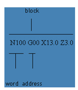
The CNC machine uses a set of rules to enter, edit, receive and output data. These rules are known as CNC Syntax, Programming format, or tape format. The format specifies the order and arrangement of information entered. This is an area where controls differ widely. There are rules for the maximum and minimum numerical values and word lengths and can be entered, and the arrangement of the characters and word is important. The most common CNC format is the word address format and the other two formats are fixed sequential block address format and tab sequential format, which are obsolete. The instruction block consists of one or more words. A word consists of an address followed by numerals. For the address, one of the letters from A to Z is used. The address defines the meaning of the number that follows. In other words, the address determines what the number stands for. For example it may be an instruction to move the tool along the X axis, or to select a particular tool.
 Most controllers allow suppressing the leading zeros when entering data. This is known as leading zero suppression. When this method is used, the machine control reads the numbers from right to left, allowing the zeros to the left of the significant digit to be omitted. Some controls allow entering data without using the trailing zeros. Consequently it is called trailing zero suppression. The machine control reads from left to right, and zeros to the right of the significant digit may be omitted.
1.3 Types of CNC codes
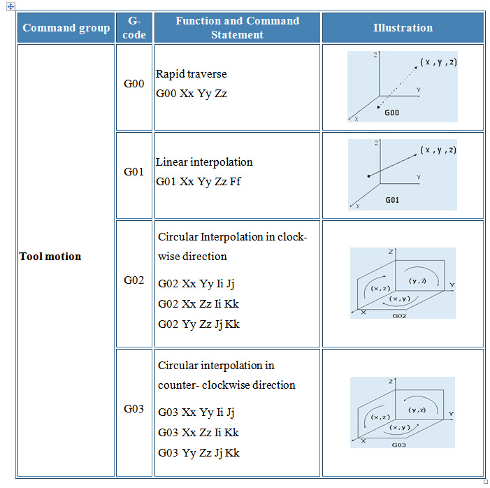
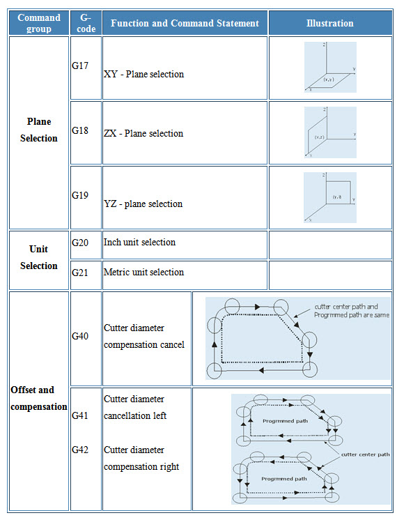
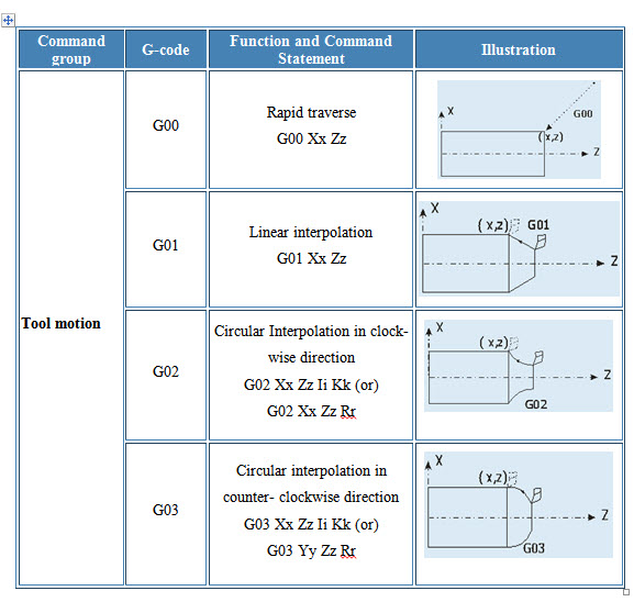
1.3.1 Preparatory codes
The term "preparatory" in NC means that it "prepares" the control system to be ready for implementing the information that follows in the next block of instructions. A preparatory function is designated in a program by the word address G followed by two digits. Preparatory functions are also called G-codes and they specify the control mode of the operation.
1.3.2 Miscellaneous codes
Miscellaneous functions use the address letter M followed by two digits. They perform a group of instructions such as coolant on/off, spindle on/off, tool change, program stop, or program end. They are often referred to as machine functions or M-functions. Some of the M codes are given below.
M00 Unconditional stop
M02 End of program
M03 Spindle clockwise
M04 Spindle counterclockwise
M05 Spindle stop
M06 Tool change (see Note below)
M30 End of program
In principle, all codes are either modal or non-modal. Modal code stays in effect until cancelled by another code in the same group. The control remembers modal codes. This gives the programmer an opportunity to save programming time. Non-modal code stays in effect only for the block in which it is programmed. Afterwards, its function is turned off automatically. For instance G04 is a non-modal code to program a dwell. After one second, which is say, the programmed dwell time in one particular case, this function is cancelled. To perform dwell in the next blocks, this code has to be reprogrammed. The control does not memorize the non-modal code, so it is called as one shot codes. One-shot commands are non-modal. Commands known as "canned cycles" (a controller's internal set of preprogrammed subroutines for generating commonly machined features such as internal pockets and drilled holes) are non-modal and only function during the call.
On some older controllers, cutter positioning (axis) commands (e.g., G00, G01, G02, G03, & G04) are non-modal requiring a new positioning command to be entered each time the cutter (or axis) is moved to another location.
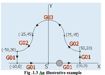
Illustrative Example Program
A contour illustrated in figure 1.3 is to be machined using a CNC milling machine. The details of the codes and programs used are given below.
Example:
|
O5678 |
Program number |
|
N02 G21 |
Metric programming |
|
N03 M03 S1000 |
Spindle start clockwise with 1000rpm |
|
N04 G00 X0 Y0 |
Rapid motion towards (0,0) |
|
N05 G00 Z-10.0 |
Rapid motion towards Z=-10 plane |
|
N06 G01 X50.0 |
Linear interpolation |
|
N07 G01 Y20.0 |
Linear interpolation |
|
N08 G02 X25.0 Y45.0 R25.0 |
Circular interpolation clockwise(cw) |
|
N09 G03 X-25.0 Y45.0 R25.0 |
Circular interpolation counter clockwise(ccw) |
|
N10 G02 X-50.0 Y20.0 R25.0 |
Circular interpolation clockwise(cw) |
|
N11 G01 Y0.0 |
Linear interpolation |
|
N12 G01 X0.0 |
Linear interpolation |
|
N13 G00 Z10.0 |
Rapid motion towards Z=10 plane |
|
N14 M05 M09 |
Spindle stop and program end |
Reference:http://nptel.iitm.ac.in/courses/Webcourse-contents/IIT-Delhi/Computer%20Aided%20Design%20&%20ManufacturingI/index.htm.
Last modified: Friday, 28 March 2014, 6:58 AM