Site pages
Current course
Participants
General
MODULE 1. Introduction to production of agricultur...
MODULE 2. Advance in material for tractor and agri...
MODULE 3. Advanced manufacturing techniques
MODULE 4. Heat treatment of steel
MODULE 5. Industrial lay out planning and quality ...
MODULE 6. Economics of process
MODULE 7. Techno economic feasibility of project r...
MODULE 8. Servo motors, drives and controllers
MODULE 9. CNC controllers for machine tools
MODULE 10. CNC programming
MODULE 11. Assembly and plant automation storage a...
LESSON ?. CNC PART PROGRAMMING II
2.1 Programming modes
In the previous section, fundamentals of programming as well basic motion commands for milling and turning have been discussed. This section gives an overview of G codes used for changing the programming mode, applying transformations etc., Programming mode should be specified when it needs to be changed from absolute to incremental and vice versa. There are two programming modes, absolute and incremental and is discussed below.
2.1.1 Absolute programming (G90)
In absolute programming, all measurements are made from the part origin established by the programmer and set up by the operator. Any programmed coordinate has the absolute value in respect to the absolute coordinate system zero point. The machine control uses the part origin as the reference point in order to position the tool during program execution (Fig. 2.1).
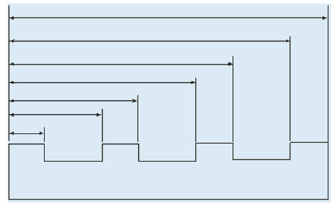
Fig. 2.1 Absolute distances measured from reference zero
2.1.2 Relative programming (G91)
In incremental programming, the tool movement is measured from the last tool position. The programmed movement is based on the change in position between two successive points. The coordinate value is always incremented according to the preceding tool location. The programmer enters the relative distance between current location and the next point (Fig. 2.2).
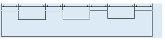
Fig. 2.2 Incremental distances measured from previous locations
2.2 Spindle control
The spindle speed is programmed by the letter 'S' followed by four digit number, such as S1000. There are two ways to define speed.
1. Revolutions per minute (RPM)
2. Constant surface speed
The spindle speed in revolutions per minute is also known as constant rpm or direct rpm. The change in tool position does not affect the rpm commanded. It means that the spindle RPM will remain constant until another RPM is programmed. Constant surface speed is almost exclusively used on lathes. The RPM changes according to diameter being cut. The smaller the diameter, the more RPM is achieved; the bigger the diameter, the less RPM is commanded. This is changed automatically by the machine speed control unit while the tool is changing positions. This is the reason that, this spindle speed mode is known as diameter speed.
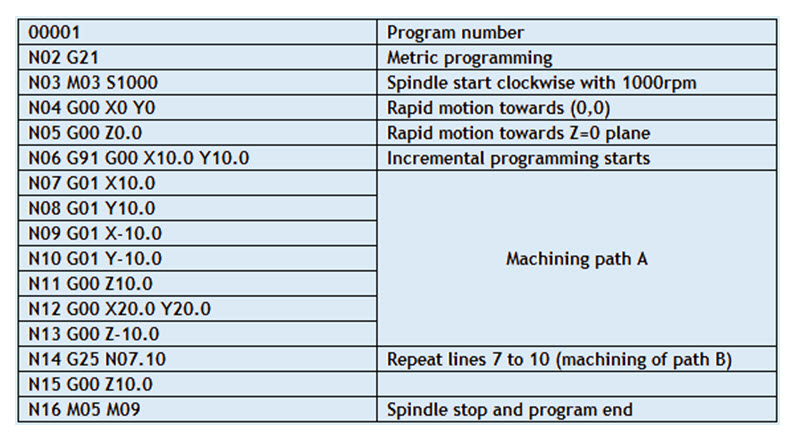
2.3 Loops and Unconditional jump (G25)
The unconditional jump is used to repeat a set of statements a number of times.
Example: N10
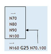
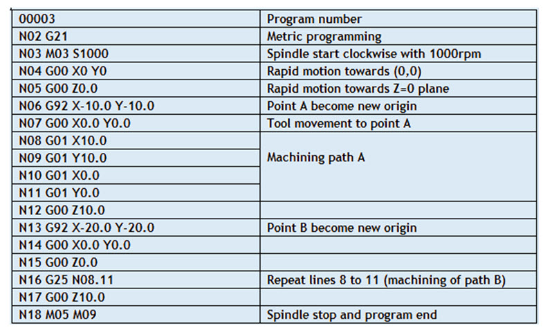
In the above example, the program statements from N70 to N100 are repeated once when the statement N160 is executed. Usually the G25 is used after a mirror statement. Illustrative example geometry and its program are given below (Fig. 2.3).
Example:
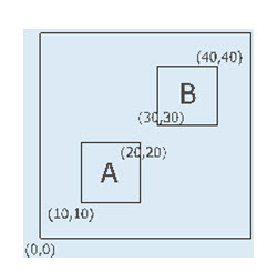
Fig. 2.3 Illustrative example for programming loops
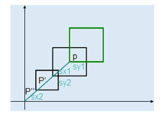
2.4 Mirroring
The mirroring command is used when features of components shares symmetry about one or more axes and are also dimensionally identical. By using this code components can be machined using a single set of data and length of programs can be reduced.
G10 cancellation of mirroring image
G11 Mirror image on X axis
G12 Mirror image on Y axis
G13 Mirror image on Z axis
Example:
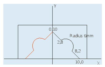
Fig. 2.4 Illustrative Example for mirroring

2.5 Shifting origin
G92 code is used to temporarily shift the origin to the reference point specified.
Example: G92 X-100 Y-80
In the above statement the x and y values gives the present values of original origin after shifting it. This is illustrated through an example (Fig. 2.5).
Example:
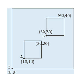
Fig. 2.5 Illustrative Example for shifting origin
2.6 Scaling
Scaling function is used to program geometrically similar components with varying sizes.
Syntax: G72 Kk, where k is the scaling factor.
The scaling command can be cancelled by using the statement G72 K1.0.
Example:
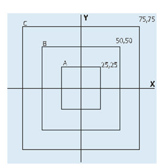
Fig. 2.6 Illustrative Example for scaling
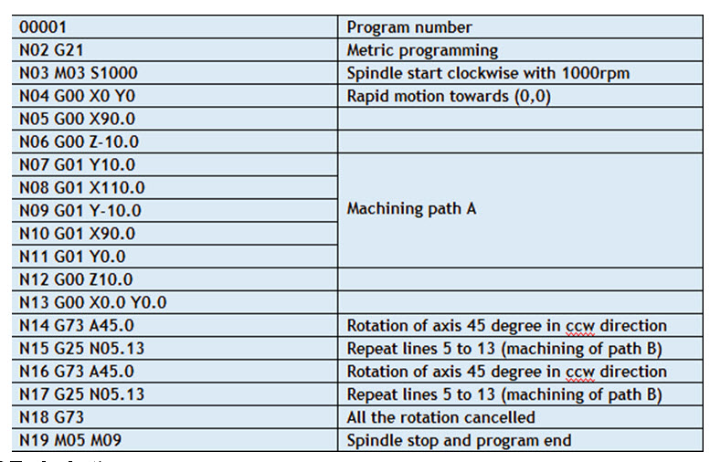
2.7 Pattern rotation
Pattern rotation is used to obtain a pattern of similar features. G73 code is used to rotate the feature to form a pattern.
Syntax G73 Aa, where 'a' is the angle of rotation. This command is cumulative, and the angle gets added up on time the program is executed. So all the rotational angle parameters should be cancelled using the code G73. The unconditional jump code G25 is used in conjunction with this code to achieve the desired rotation.
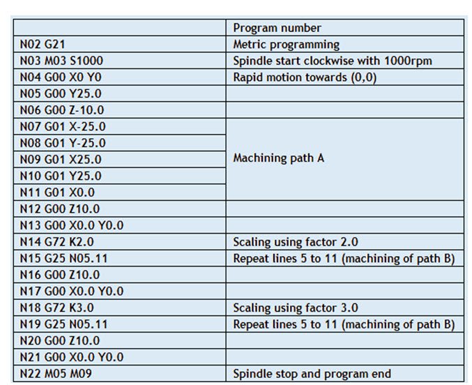
The following example (Figure 2.7) depicts the case of a pattern which needs to be programmed through G73.
Example:
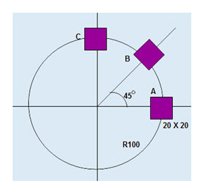
Fig. 2.7 Illustrative Example for Pattern rotation
2.8 Tool selection
Tool selection is accomplished using 'T' function followed by a four digit number where, first two digits are used to call the particular tool and last two digits are used to represent tool offset in the program. The tool offset is used to correct the values entered in the coordinate system preset block. This can be done quickly on the machine without actually changing the values in the program. Using the tool offsets, it is easy to set up the tools and to make adjustments.
Feed rate control
Cutting operations may be programmed using two basic feed rate modes:
1. Feed rate per spindle revolution
2. Feed rate per time
The feed rate per spindle revolution depends on the RPM programmed.
Reference:
Last modified: Monday, 16 September 2013, 4:29 AM