Site pages
Current course
Participants
General
MODULE 1. Introduction to production of agricultur...
MODULE 2. Advance in material for tractor and agri...
MODULE 3. Advanced manufacturing techniques
MODULE 4. Heat treatment of steel
MODULE 5. Industrial lay out planning and quality ...
MODULE 6. Economics of process
MODULE 7. Techno economic feasibility of project r...
MODULE 8. Servo motors, drives and controllers
MODULE 9. CNC controllers for machine tools
MODULE 10. CNC programming
MODULE 11. Assembly and plant automation storage a...
LESSON ?. CNC PART PROGRAMMING III
3.1 Tool Radius Compensation
The programmed point on the part is the command point. It is the destination point of the tool. The point on the tool that is used for programming is the tool reference point. These points may or may not coincide, depending on the type of tool used and machining operation being performed. When drilling, tapping, reaming, countersinking or boring on the machining center, the tool is programmed to the position of the hole or bore center - this is the command point.
When milling a contour, the tool radius center is used as the reference point on the tool while writing the program, but the part is actually cut by the point on the cutter periphery. This point is at 'r' distance from the tool center. This means that the programmer should shift the tool center away from the part in order to perform the cutting by the tool cutting edge. The shift amount depends upon the part geometry and tool radius. This technique is known as tool radius compensation or cutter radius compensation.
In case of machining with a single point cutting tool, the nose radius of the tool tip is required to be accounted for, as programs are being written assuming zero nose radius. The tool nose radius center is not only the reference point that can be used for programming contours. On the tool there is a point known as imaginary tool tip, which is at the intersection of the lines tangent to the tool nose radius.
Cutter compensation allows programming the geometry and not the tool path. It also allows adjusting the size of the part, based on the tool radius used to cut part. This is useful when cutter of the proper diameter is not found. This is best explained in the Figure 3.1.
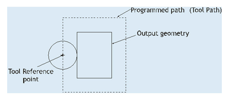
Fig 3.1. Cutter diameter compensation
The information on the diameter of the tool, which the control system uses to calculate the required compensation, must be input into the control unit's memory before the operation. Tool diameter compensation is activated by the relevant preparatory functions (G codes) as shown in Fig. 3.2.
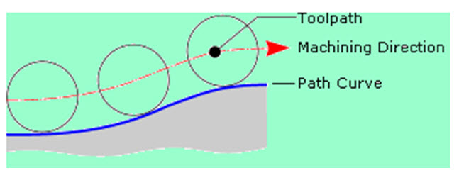
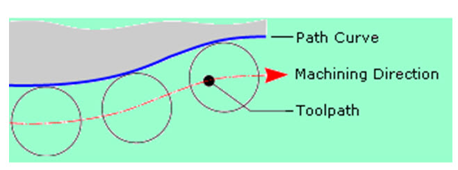
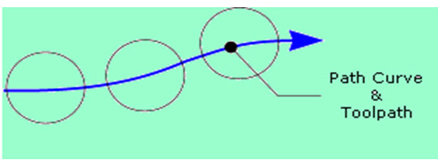
Compensation for tool radius can be of either right or left side compensation. This can be determined by direction of tool motion. If you are on the tool path facing direction of tool path and if tool is on your left and work piece is on your right side then use G41 (left side compensation). For, reverse use other code G42 (Right side compensation). Both the codes are modal in nature and remain active in the program until it is cancelled by using another code, G40.
Offset Direction = Left (G41)
Offset Direction = Right (G42)
Offset Direction = Off (G40)
3.2 Ramp on/off motion
When activating cutter radius compensation, it must be ensured that the slides will first make a non-cutting move to enable the correct tool and workpiece relation to be established. A similar move is necessary prior to cancellation of the radius compensation. These non-cutting moves are referred as "ramp on" and "ramp off" respectively. Fig. 3.3 shows the ramp on motion for different angles of approach.
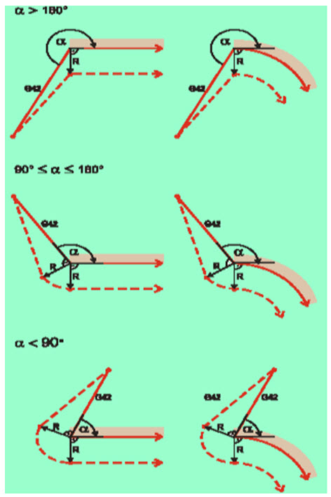
Figure 3.3. Ramp up motion
3.3 Subroutines
Any frequently programmed order of instruction or unchanging sequences can benefit by becoming a subprogram. Typical applications for subprogram applications in CNC programming are
Repetitive machining motions
Functions relating to tool change
Hole patterns
Grooves and threads
Machine warm-up routines
Pallet changing
Special functions and others
Structurally, subprograms are similar to standard programs. They use the same syntax rules. The benefits of subroutines involve the reduction in length of program, and reduction in program errors. There is a definition statement and subroutine call function.
Standard sub-routine
N10
N20
N30
….
N70 G22 N5
N80
N90
….
N100 G24
….
N160 G20 N5
In the above example G22 statement defines the start block of the sub-routine and G24 marks the end of the sub-routine statement. The subroutine is called by another code G20 identified by the label N5.
Parametric subroutine
..
G23 N18
G01 X P0 Y P1
..
G21 N18 P0=k10 P1=k20
In the above example G23 starts the subprogram label and starts the definition, and the parameters P0, P1 are defined for values of x and y. The G21 statement is used to call the subroutine and to assign the values to the parameters.
3.4 Canned Cycles
A canned cycle is a preprogrammed sequence of events / motions of tool / spindle stored in memory of controller. Every canned cycle has a format. Canned cycle is modal in nature and remains activated until cancelled. Canned cycles are a great resource to make manual programming easier. Often underutilized, canned cycles save time and effort.
3.4.1 Machining a Rectangular pocket
This cycle assumes the cutter is initially placed over the center of the pocket and at some clearance distance (typically 0.100 inch) above the top of the pocket. Then the cycle will take over from that point, plunging the cutter down to the "peck depth" and feeding the cutter around the pocket in ever increasing increments until the final size is attained. The process is repeated until the desired total depth is attained. Then the cutter is returned to the center of the pocket at the clearance height as shown in fig. 3.4
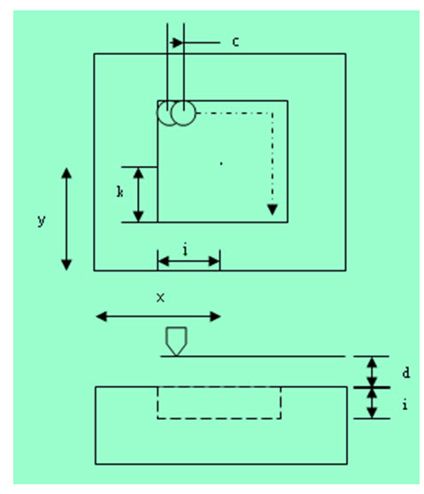
Fig. 3.4 Pocket Machining
The overall length and width of the pocket, rather than the distance of cutter motion, are programmed into this cycle.
The syntax is : G87 Xx Yy Zz Ii Jj Kk Bb Cc Dd Hh Ll Ss (This g code is entirely controller specific and the syntax may vary between controller to controller).
Description:
x,y - Center of the part
z - Distance of the reference plane from top of part
i - Pocket depth
j,k - Half dimensions of the target geometry (pocket)
b - Step depth
c - Step over
d - Distance of the reference plane from top of part
h - Feed for finish pass
l - Finishing allowance
s – Speed
For machining a circular pocket, the same syntax with code G88 is used.
3.4.2 Turning Cycles
The G80 command will make the tool move in a series of rectangular paths cutting material axially until the tool tip reaches target point P1 where the cycle ends as shown in fig. 3.5. Cutting movements will be at the cutting feed rate. All other movements will be at rapid traverse rate.
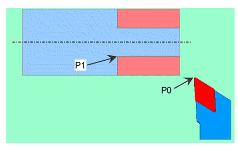
Fig. 3.5 Turning Cycle (Straight cutting)
The syntax is G80 Xx Zz Ff
3.4.3 Roughing Cycle
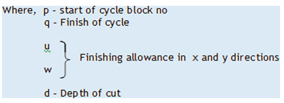
In roughing cycle, the final finishing cycle profile is used to perform the roughing operation for the higher material removal rate. The syntax for the roughing cycle is given below.
G81 Pp Qq Uu Ww Dd Ff Ss
3.5 The APT Programming Language
The APT (Automatically Programmed Tool) programming language was developed in early 1960s to assist engineers in defining the proper instructions and calculations for NC part programming. A great strength of APT is its ability to perform precise calculations for complicated tool paths when contouring on a three dimensional surface in a multi- axis programming mode. Now APT has become obsolete. Please click here to know more about APT. Automatic generation of NC code is dealt in this page
Last modified: Friday, 28 March 2014, 7:00 AM