Site pages
Current course
Participants
General
MODULE 1. BASIC CONCEPTS
MODULE 2. SYSTEM OF FORCES
MODULE 3.
MODULE 4. FRICTION AND FRICTIONAL FORCES
MODULE 5.
MODULE 6.
MODULE 7.
MODULE 8.
LESSON 15.
15.1 INTRODUCTION
A plane truss or frame consists of several bars laying in one plane and connected by hinges or pins at their ends so as to provide a stable configuration. Frames are used in the roofs of sheds at Railway platform, workshops and in industrial buildings, bridges etc. Plane trusses are made of short thin members interconnected at hinges into triangulated patterns.
-
The truss can have only hinged and roller supports.
-
In field, usually joints are constructed as rigid by welding.
For analysis purpose we assume that the following conditions are satisfied.
(i) All the members are connected together at their ends by pin joints which are absolutely frictionless.
(ii) All loads and reactions act on the truss only at the joints.
(iii) The longitudinal centroidal axes of the members are absolutely straight, concident with the appropriate lines joining the joint centres and lie in the same plane of the lines of action of the loads and reactions.
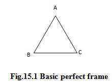
The simplest frame is a triangle (Fig.15.1), consists of three members pin-jointed to each other. This can be easily analyzed by the condition of equilibrium. This frame is called the basic perfect frame. It has three members AB, BC and CA and three joints A, B and C.
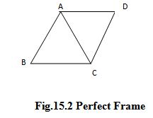
Suppose we add two members AD and CD and a joint D to this basic perfect frame, we get a frame (Fig.15.2) which can also be analyzed by the condition of equilibrium. This frame is called a perfect frame.
 Suppose we add two members and a joint to this frame as shown in Fig.15.3, we again got a perfect frame.
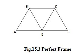
In this way we can go on adding any number of sets and can obtain a perfect frame.
15.2 TYPES OF FRAMES
Following are the types of frames:
(a) Perfect Frame
(b) Deficient or Imperfect Frame
(c) Redundant Frame
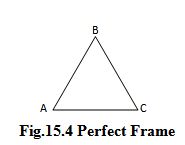
(a) Perfect Frames :- Simplest perfect frame is a triangular assemblage of three member AB, BC, CA meeting at joints B, C and A as shown in Fig.15.4
Mathematically,
m = number of members
j = number of joints
Then m = 2 j – 3 is the condition for the frame to be a perfect frame.
- Hence for a stable frame the minimum number of members required = Twice the number of joints minus three.
- If the number provided is less than the above requirement equation then frame will not be stable.
For the Fig.15.4, m = 3, j = 3
m = 2j – 3
3 = 2 × 3 – 3
3 = 3 condition is satisfied.
Now consider the frame in Fig.15.5
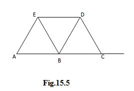
Here m = 7, j = 5
m = 2j – 3
7 = 2 × 5 – 3
7 = 7
Hence the frame is perfect frame.
(a) Imperfect Frames :- (a) When the numbers are less than that required by equation m = 2j – 3 then frame is called imperfect or deficient frame. Such frame, cannot resist geometrical distortion under the action of loads.
(b) Redundant Frames :- If the number of members are more than that required by equation m = 2j -3, then such frames will be called as redundant frames.
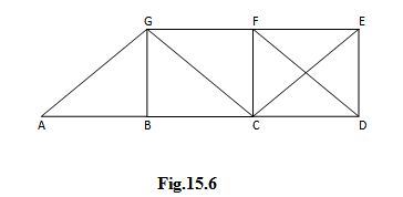
In Fig.15.6,
m = 12, j = 7
m = 2j – 3
12 = 2 × 7 – 3
12 = 14 – 3 = 11
Hence, the frame is redundant to a single degree, because one member is more.
In general let a frame have j joints and n members.
If n = 2j – 3, then the frame is perfect frame.
If n < 2j – 3, then the frame is deficient frame.
If n > 2j – 3, then the frame is redundant frame.
A perfect frame can always be analyzed by the condition of equilibrium. While a redundant frame cannot be fully analyzed by the condition of equilibrium. We will discuss the analysis of perfect frames only.
15.3 REACTIONS AT SUPPORT
Frames are usually provided with either
(i) Roller Supports
(ii) Hinged Support
(iii) Fixed Support
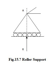
(i) Roller Support: Fig. 15.7 consists of support which is known as roller support. It is always a normal reaction R perpendicular to the surface of rolling. This support always gives one reaction component in perpendicular direction.
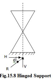
(ii) Hinged Support: This is the support at which inclined reaction R is developed. It has two components one is in vertical direction i.e. V and other is in horizontal direction which is H. Hence, hinged support always offers offers two reaction components V and H.
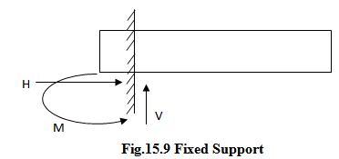
(iii) Fixed Support: Fig. 15.9 shows a fixed support at which three reaction components are developed. One is in vertical direction i.e. V, one is in horizontal direction i.e. H and one is a moment M.
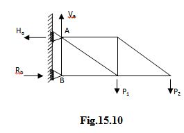
In the cantilever frame shown in Fig. 15.10 the roller base at B is vertical and hence the reaction at this support is horizontal.
At a hinged support, the direction and the line of action of reaction will depend upon the load system on the structure.
To determine the reactions
Reactions at the supports of a structure can be determined by the conditions of equilibrium. The external load system applied on the structure and the reactions at the supports must form a system in equilibrium.
Consider the cantilever truss shown in Fig.15.11. The truss is provided with a hinged support at A and a roller support at E. The roller base at E being vertical the reaction at E is horizontal. Hence there will be no vertical reaction at E.
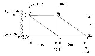
Fig.15.11
Taking moments about A.
He × 4 = (60 + 40) 3 + (30 × 6)
He = 120 KN →
Total applied vertical force = 60 + 40 +30 = 130 KN ↓
Therefore, vertical reaction at A = Va = 130 KN ↑
Resolving the forces horizontally, we get
Ha = 120 KN ←
Thus the reaction at A consists of a vertical component Va = 130 KN ↑ and a horizontal component
Ha = 120 KN ←
Now consider the truss shown in Fig.15.12 provided with a hinged support at A and a roller support at G. The roller base at G is horizontal and hence the reaction at G is entirely vertical. There will be no horizontal reaction at G.
Taking moments about A
Vg× 8 = ( 20 × 3) + ( 30 × 2) + ( 40 × 4) + ( 60 × 6)
Therefore, Vg = 80 KN ↑
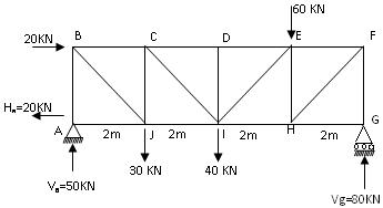
Fig.15.12
Total applied vertical force = 30 + 40 + 60 = 130 KN ↓
Therefore, vertical reaction at A = Va = 130 – 80 = 50 KN ↑
Total applied horizontal force = 20 KN →
Therefore, Horizontal reaction at A = Ha = 20 KN ←
To determine which member of a truss do not carry forces
In a truss carrying a load system some members may not carry forces. Such members can be identified by using the following principles.
(a) A single force cannot form a system in equilibrium. Means if there is only one force acting at a joint, then for the equilibrium of the joint, this force will be equal to zero as shown in Fig. 15.13.
P = 0
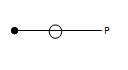
Fig.15.13
(b) If two forces act at a joint, then for the equilibrium of the joint these two forces should act along the same straight line. The two forces will be equal and opposite. If these two forces are not along the same line. Then for equilibrium of the joint each force equals to zero as shown in Fig. 15.14.
P = 0 and Q = 0
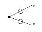
Fig.15.14
(c) If three forces act at a joint and two of them are along the same straight line, then for the equilibrium of the joint, the third force should be equal to zero as shown in Fig. 15.15.
R = 0
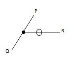
Fig. 15.15
For example, in the truss shown in Fig. 15.16
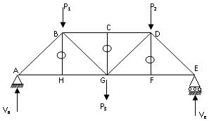
Fig. 15.16
Consider the joint H. Forces at this joint are
Pha in the member HA.
Phg in the member HG.
Phb in the member HB.
Since Pha and Phg are in the same straight line, Phb = 0. Similarly, Pcg = 0 and Pfd = 0.
Assumptions in truss analysis
Trusses are analyzed based on the following assumptions:
(i) Each member of the truss is connected at its end by frictionless pins.
(ii) The truss is loaded as well as supported only at its joints.
(iii) The forces in the members of the truss are axial.
(iv) The self-weight of the members is neglected.
These assumptions only lead to idealization of a truss.
In reality the steel trusses are not exactly pin-jointed. They are fabricated by riveting, bolting or welding the ends of the members to gusset plates.
The truss joints are semi-rigid in reality and can transmit moments unlike frictionless pinned joints.
In many situations the loads are not applied exactly at the joints.
It should be remember that in an actual truss the centroidal axes of the members are not really concurrent at a joint thus inducing bending moments in the member.
Last modified: Tuesday, 10 September 2013, 7:33 AM