Site pages
Current course
Participants
General
Module 1_Fundamentals of GW
Module 2_Well Hydraulics
Module 3_Design, Installation and Maintenance of W...
Module 4_Groundwater Assessment and Management
Module 5_Principle, Design and Operation of Pumps
Module 6_Performance Characteristics, Selection an...
Keywords
12 April - 18 April
19 April - 25 April
26 April - 2 May
Lesson 24 Centrifugal Pumps
24.1 Operating Principle of Centrifugal Pumps
Centrifugal pump is defined as ‘a mechanical device to raise liquids from a lower elevation to a higher elevation by creating pressure with the help of centrifugal action’. If the liquid of a container is rotated with a sufficiently high velocity so as to enable it to rise beyond the walls of the container, and if more liquid is constantly supplied at the centre by a suitable means, the tendency of the liquid would be to flow out as shown in Fig. 24.1. Such a system in principle is a centrifugal pump.
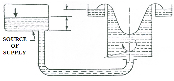
Fig. 24.1. Working principle of centrifugal pumps. (Source: Lal, 1969)
Whirling motion is imparted to the liquid by means of backward curved blades mounted on a wheel known as the impeller. The liquid to be pumped enters the impeller at its center, which is technically known as the eye of the pump, and discharges into the casing surrounding the impeller. The pressure head developed by centrifugal action is entirely due to the velocity imparted to the liquid by the rotating impeller, and not due to any displacement or impact.
On the other hand, if the liquid is flowed into the tank over the rim from an outside source at a higher elevation, and were drawn out at the centre, the flow being inward, the system will constitute a Francis Water Turbine in principle. The pump is usually named after the type of its casing (i.e., volute pump or diffuser pump). Diffuser casing is equipped with vanes and its design has been adopted from the Francis turbine. Therefore, the pump provided with a diffuser casing is also known as a turbine pump. Vertical turbine pumps (usually multi-stage), which are particularly suited for pumping water from deep wells, are often called deep well pumps.
24.1.1 Analysis of Flow through Impeller
In runners of turbines and in impellers of pumps, the flow of fluid is usually a combination of : (a) circulatory flow (i.e., flow in concentric circles), and (b) radial flow (i.e., flow involving a change of distance from the axis of rotation). The path resulting from the superimposition of these two motions is in the form of a spiral. In a centrifugal pump, water enters through an opening provided at the centre and leaves at the periphery. Guide vanes are made of spiral shape to enable water to have both circulatory and radial flows inside the impeller.
As the radius increases from inlet to outlet, the area across the flow must also increase (Fig. 24.2), and consequently the relative velocity decreases so that  and
and ![]() where q = quantity of water flowing per second, and a1, a2 are areas across flow at the inlet and outlet, respectively between two consecutive blades.
where q = quantity of water flowing per second, and a1, a2 are areas across flow at the inlet and outlet, respectively between two consecutive blades.
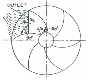
Fig. 24.2. Line diagram of impeller blades. (Source: Lal, 1969)
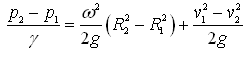
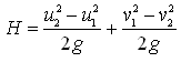
Therefore, pressure difference due to the change of kinetic energy is given as  per unit weight of water. Also, pressure difference (ΔP) due to the centrifugal head can be expressed as:
 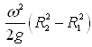 , where, R1 and R2 are inner radius and outer radius of the impeller, respectively. This pressure difference is due to cylindrical vortex only.
Therefore, the total pressure difference due to two flows (i.e., circulatory and radial) or due to spiral vortex will be:
 (24.1)
 (24.2)
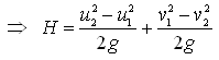
Where, H = head developed by the impeller, u1 = peripheral velocity of water at the inlet of the impeller, and u2 = peripheral velocity of water at the outlet of the impeller.
24.1.2 Example Problems
Problem 1: A certrifugal pump impeller has an inner diameter of 50 cm and its outer diameter is twice the inner diameter. Calculate the speed of the impeller (in rpm) at which the lifting of water will commence against a head of 15 m.
Solution: Given: R1 = 50/2 cm = 25 cm = 0.25 m, and
R2 = 100/2 cm = 50 cm = 0.50 m.
We know that Centrifugal Head =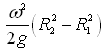
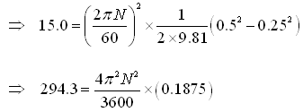
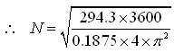 =378.5 rpm, Ans.
Problem 2: Find the head developed by the impeller in the above problem, if the relative velocities of water at the inlet and outlet of the impeller are 7.5 and 5.4 m/s, respectively.
Solution: We have, v1 = 7.5 m/s, v2 = 5.4 m/s, and Centrifugal head (i.e., head developed by the centrifugal action) = 15.0 m.
From Eqn. (24.2), the head developed by the impeller (H) is given as:
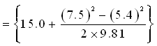 m
m
=(15.0+1.38) m=16.38 m, Ans.
24.2 Components of a Centrifugal Pump
There are a variety of centrifugal pumps available in the market. However, commonly used centrifugal pumps have two basic components: a rotary element called impeller and a stationary element known as casing. Along with these two major components, it may also have some other components such as pump inlet, pump outlet, suction valve, delivery valve, priming device, foot valve with a screen and/or pressure gauge (Fig. 24.3). A brief description about these components is given below.
(1) Impeller: It is a rotor, which is provided with a series of backward curved blades. It is mounted on a shaft, which is coupled to an external source of energy, which imparts the required energy to the impeller thereby making it to rotate.
(2) Casing: It is an air-tight chamber which surrounds the impeller and is usually in the form of a spiral or volute curve with a cross-sectional area increasing towards the discharge opening.
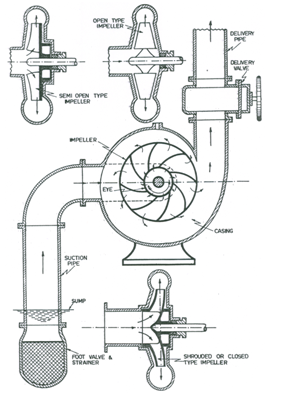
Fig. 24.3. Components of a centrifugal pump.
(Source: Modi and Seth, 1998)
(3) Pump Inlet (Suction Port): Liquid enters through the suction port or the pump inlet and flows into the pump casing. In centrifugal volute pumps the suction ports are located axially.
(4) Suction Valve (or Reflux Valve): Its main purpose is to retain water in the pump and the suction pipe section between the pump and the reflux valve, to help priming. The reflux valve is used when pumps are directly connected to the suction pipe. In case of pumping to overhead tanks and long distance conveyance, the reflux valves are used in the delivery side also so as to allow flow in the forward direction only, thereby checking the return flow and preventing water hammering.
(5) Pump Outlet (Delivery Port): Liquid present inside the pump casing is thrown out of the casing and exits the pump through the delivery port or pump outlet. The delivery ports are placed centrally in radial direction in volute pumps.
(6) Delivery Valve: Sometimes centrifugal pumps are fitted with a one-way valve on the delivery pipe to regulate pump discharge and/or help in priming.
(7) Priming Device (optional): It is an optional component of a centrifugal pump. A priming device in a centrifugal pump eliminates the need for external priming mechanism and when it is provided in a centrifugal pump, it is known as a self-priming centrifugal pump. When the pump is shut down, the liquid in it drains out of the suction line. At the bottom of the casing in a priming device, a small quantity of liquid is retained. When the pump is started again, this water is pushed by the impeller out the discharge line, along with some air. This creates a vacuum at the impeller inlet, which draws liquid up the suction line. The priming cycle continues until all of the air is pushed out. Salient self-priming pumps and self-priming devices are discussed in Lesson 29.
(8) Foot Valve with a Screen (optional): The suction side of the pump consists of foot valve at the bottom of suction line. The foot valve is a one-way valve which helps to prevent the trash from entering the suction side and at the same time retains water in the suction line to help priming of the pump.
(9) Pressure Gauges (optional): A pressure gauge on the discharge side close to the outlet of the pump helps to diagnose pump system problems. It is also useful to have a pressure gauge on the suction side; the difference in pressure is proportional to the total head.
24.3 Types of Centrifugal Pumps
Centrifugal pumps possess some characteristic features based on which they are classified. These characteristic features are as follows:
(i) Working head,
(ii) Casing design (type of energy conversion),
(iii) Number of impellers (or, number of stages),
(iv) Relative direction of flow through the impeller,
(v) Number of entrances to the impeller (or, type of suction inlet),
(vi) Disposition of pump shaft,
(vii) Split of casing (Horizontally-split casing pumps and Vertically-split casing pumps),
(viii) Connection of the pump to the prime mover (Close-coupled/Monoblock centrifugal pumps, and Flexible-coupled centrifugal pumps),
(ix) Type of impeller (or, type of liquid handled), and
(x) Specific speed of the pump.
Note that the first characteristic feature is a commercial classification of centrifugal pumps from the viewpoint of their utility, but the characteristic features under (ii) to (ix) are all practical considerations each governing an important constructional feature of the pump. The last feature is a solely theoretical aspect and provides a technically sound basis for the absolute classification of centrifugal pumps.
24.3.1 Types of Centrifugal Pumps Based on Working Head
It is the head against which water is delivered by a pump. Based on the working head, centrifugal pumps could be classified as follows:
(1) Low-Head Centrifugal Pumps: They can produce heads up to 15 m. The impeller is usually surrounded by a volute and there are no guide vanes. The shaft is generally horizontal and water may enter the impeller from one or both sides depending on the quantity of water to be delivered.
(2) Medium-Head Centrifugal Pumps: They are capable of generating heads as high as 40 m. They are usually provided with guide vanes. Water may enter from one or both sides depending on the quantity of water to be pumped.
(3) High-Head Centrifugal Pumps: They can generate heads greater than 40 m. They are generally multi-stage pumps because an ordinary single impeller cannot build up such a high pressure. High-head centrifugal pumps may be horizontal or vertical; the latter is mostly used in deep wells.
24.3.2 Types of centrifugal Pumps Based on Casing Design
Pump casing should be so designed as to minimize the loss of kinetic head through eddy formation, etc. Efficiency of the pump largely depends on the type of casing. In general, the casings are of three types as shown in Figs. 24.4(a, b, c) and the pump is named after the type of casing it has. They are: (i) volute pump, (ii) volute pump with vortex chamber (or double volute pump), and (iii) diffuser pump (or turbine pump). A brief description about these pump types is given below.
(i) Volute Pump: It has a volute casing (spiral shaped casing, which is known as volute chamber) into which the impeller discharges water at a high velocity. The shape of the casing is such that the cross-sectional area of the flow around the impeller periphery gradually increases from the tongue towards the delivery pipe.
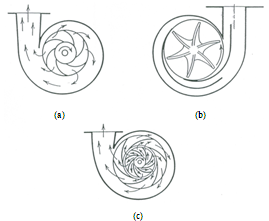
Fig. 24.4. Types of centrifugal pump casings: (a) Single volute; (b) Double volute casing; (c) Diffuser casing. (Source: James, 1988)
(ii) Volute Pump with Vortex Chamber (or Double Volute Pump): A subsequent improvement in the simple volute casing was made by providing a circular chamber between the impeller and the volute chamber. The circular chamber that acts as a diffuser is known as a vortex or whirlpool chamber, and such a pump is called volute pump with vortex chamber. Almost all the volute pumps are single-stage type, with horizontal shafts irrespective of the shape of impeller.
(iii) Diffuser Pump: In this pump, the impeller is surrounded by a series of ‘guide vanes’ (stationary vanes) or ‘diffusers’ mounted on a ring called ‘diffuser ring’. Diffuser pump is also known as a turbine pump. Diffuser pumps may be either horizontal or vertical shaft type.
24.3.3 Types of Centrifugal Pumps Based on Number of Impellers
Based on the number of impellers per shaft, centrifugal pumps are classified as: (i) single-stage centrifugal pump, and (ii) multi-stage centrifugal pump. They are succinctly discussed below.
(i) Single-Stage Centrifugal Pump
Single-stage centrifugal pumps have only one impeller fitted to the pump shaft. Such a pump is generally horizontal, but can be vertical also. It is usually a low-lift (low-head) pump. Vertical turbine pumps can have 1 to about 25 stages.
(ii) Multi-Stage Centrifugal Pump
Multi-stage centrifugal pumps have two or more identical impellers fitted to a single shaft (Fig. 24.5) and enclosed in the same casing. Thus, pressure is built up in steps. The impellers are surrounded by guide vanes and the water is led through a by-pass channel from the outlet of one stage to the entrance of the next until it is finally discharged into a wide chamber from where it is pushed on to the delivery pipe.
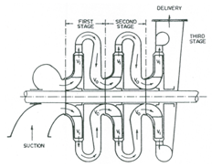
Fig. 24.5. Configuration of a three-stage centrifugal pump.
(Source: Modi and Seth, 1998)
Multi-stage pumps are used essentially for high working heads and the number of stages depends on the head required. Usually, not more than 15 stages are employed for ordinary multi-stage centrifugal pumps. According to the number of impellers fitted to a single shaft, a multi-stage pump is designated as two-stage, three-stage, four-stage, and so on. Multi-stage vertical turbine pumps can develop heads up to about 1500 m. However, some specially designed multi-stage pumps can have a discharge up to 946 L/s and can develop heads up to about 2100 m. Remember that for a given type of impeller, the head and power requirements of a multi-stage pump increase in direct proportion to the number of stages. However, the discharge and efficiency of a multi-stage pump are almost the same as for the single-stage pump operating alone.
Discharge and Head of Multi-Stage Pumps: As the liquid passes through each impeller, the absolute velocity of the liquid increases to V1, and in each connecting passage, the absolute velocity decreases to Vo, but the pressure head continuously increases. If H1 and H2 are the pressure heads gained by the liquid in each impeller and the surrounding guide vanes, respectively, then the pressure head imparted on the liquid at each stage is Hm = (H1 + H2). Now, if there are n impellers, then the total head (H) developed by the multi-stage pump will be:
![]() (24.3)
(24.3)
This is because at each stage, the pressure head will be raised by the same amount. Moreover, since the same liquid flows through each impeller, the discharge of a multi-stage pump is the same as the discharge passing through each impeller of series.
24.3.4 Types of Centrifugal Pumps Based on Relative Direction of Flow
On the basis of the direction of flow of liquid through the impeller, the centrifugal pumps are classified as: (i) radial flow pump, (ii) axial flow pump, and (iii) mixed flow pump as shown in Figs. 24.6(a, b, c).
(i) Radial Flow Pump: In this pump, liquid flows through the impeller in the radial direction only. Generally, all centrifugal pumps are manufactured with radial flow impellers.
(ii) Axial Flow Pump: In this pump, the flow through the impeller is in the axial direction only. Axial flow pumps are designed to deliver very large quantities of water at relatively low heads. Thus, they are ideally suited for irrigation purposes. Although the axial pump is a rotodynamic pump, it is hardly justifiable to call it a centrifugal pump, because the centrifugal force is not used for the generation of pressure. Pressure is developed by flow of liquid over blades of aerofoil section just as the wings of an aeroplane produce the lift. The action is just the opposite of a propeller turbine.
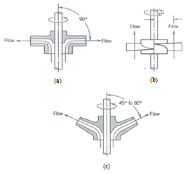
Fig. 24.6. Types of centrifugal pumps based on realtive direction of flow through the impeller: (a) Radial flow pump; (b) Axial flow pump; (c) Mixed flow pump. (Source: James, 1988)
(iii) Mixed Flow Pump: In this pump, the liquid flows through the impeller axially as well as radially; that is there is a combination of radial flow and axial flow. Some mixed flow impellers look like a screw and are known as screw impellers. A mixed flow impeller is just a modification of radial flow type enabling it to pump a large quantity of water. As such, mixed flow pumps are generally used where a large quantity of liquid is to be discharged at a low head. In older designs, a large quantity of water was delivered by running several pumps in parallel, but this arrangement is now obsolete.
24.3.5 Types of Centrifugal Pumps Based on Number of Entrances to the Impeller
Based on the number of entrances to the impeller, the centrifugal pumps are classified as: (i) single suction (entry) pump, and (ii) double suction (entry) pump. In the single suction pump, water from a suction pipe enters into the impeller from one side of the impeller only. However, in a double suction pump, water enters into the impeller from both sides of the impeller. The double suction centrifugal pump is suitable for pumping large quantities of liquid, because it provides a larger inlet area. The provision of double suction/entry has an added advantage that the axial thrust on the impeller is neutralized.
24.3.6 Types of Centrifugal Pumps Based on Disposition of Shaft
The shaft of a centrifugal pump can be disposed horizontally or vertically, and accordingly the centrifugal pump is called a horizontal centrifugal pump or vertical centrifugal pump. Normally, centrifugal pumps are designed with horizontal shafts and impellers are mounted vertically on the shafts. They are most commonly used for irrigation. Vertical centrifugal pumps have vertical shafts and impellers are mounted horizontally on the shafts. Vertical disposition of the shaft provides an economy in space occupied, and hence vertical pumps are suitable for deep wells, mines, etc. They can also be used for irrigation purposes. Note that the volute-type vertical centrifugal pumps may be either submerged or exposed. The body of an exposed vertical centrifugal pump is usually set in a sump at a level that can accommodate the suction lift.
24.3.7 Types of Centrifugal Pumps Based on Based on Type of Impeller
Depending on the type and viscosity of liquid to be pumped, the pump may have a closed, semi-open, or open impeller [Figs. 24.7(a, b, c)]; accordingly the centrifugal pumps are classified as: (i) closed impeller pump, (ii) semi-open impeller pump, and (iii) open impeller pump. Each of these impeller types may have ferrous, non-ferrous, or stone-coated impeller to resist the chemical effect of the liquid being pumped.
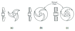
Fig. 24.7. Types of centrifugal pumps based on type of impeller: (a) Closed impeller pump; (b) Semi-open impeller pump; (c) Open impeller pump. (Source: James, 1988)
(i) Closed Impeller Pump
Closed impeller pumps have shrouded impellers. Shrouded or closed impeller is the one in which the vanes are covered with metal plates (also called ‘shrouds’) on both sides. These plates (shrouds) are known as crown plate (i.e., top plate) and base plate (i.e., bottom plate). The closed impeller provides better guidance for the liquid and is the most efficient. However, this type of impeller is most suited when the liquid to be pumped is free from debris and other such impurities. That is, the closed impeller is meant for handling non-viscous liquids such as ordinary water, hot water, hot oil and chemicals like acids, etc.
Material of the impeller should be selected according to the chemical properties of the liquid to be pumped. For example, for hot water at a temperature greater than 150 oC, cast steel impeller is recommended. Non-ferrous (e.g., gun metal) impellers are used for chemicals or brackish water, which are liable to corrode a ferrous surface. For pumping acids, the impeller and all inside surfaces in contact with liquid should be coated with stone. On the other hand, for pumping ordinary water, impellers may be made of bronze or cast iron. Impellers for light duty could be made of rigid plastic materials.
(ii) Semi-Open Impeller Pump
This type of pump is equipped with an impeller having a shroud on one side only, i.e., the vanes have only the base plate and there is no crown plate. It is used for viscous liquids such as sewage water, paper pulp, sugar molasses, etc. In order to minimize the chances of impeller clogging, the number of vanes is reduced and their height is increased while designing a semi-open impeller. Sewage pumps (also called ‘non-clog pumps’) are meant for handling sewage water containing solid particles, rags and other impurities. Hence, they are made without any protuberances around which rags could wrap and catch. They have impeller blades which are well rounded at their entrance ends and have large passage-ways between the vanes. The number of impeller blades is small, usually not more than two. They are always of the single suction type because the shaft extends through the eyes of the impeller in double-suction pumps, thereby creating an easy place for rags to catch and wrap, and thus clogging the pump.
The non-clog pumps for paper stock and other similar materials have open-type impellers, with entrance blades especially designed to prevent separation of stock and water. The choice of impeller material is dependent on the chemical nature of the liquid to be handled. Non-clog pumps must be heavily constructed mechanically in order to provide satisfactory service.
(iii) Open Impeller Pump
Open impeller pumps have the impellers which are not provided with any shroud, i.e., the vanes have neither the crown plate nor the base plate; the vanes are attached to a central hub. These are used in dredgers and elsewhere for handling a mixture of water, sand, clay and pebbles, wherein the solid contents may be as high as 25%. The open impeller is meant for performing very rough duty. It is generally made of forged steel. Its service life depends on the type of material handled, and it may be as small as 40-50 hours, or in some cases it may vary from 500 to 1000 hours.
24.3.8 Types of Centrifugal Pumps Based on Specific Speed
The specific speed is a sound basis for a technical classification of centrifugal pumps. It is the only characteristic index of a pump when several impellers can be used for the same head and capacity. It should be noted that the performance and dimensional proportions of pumps having same specific speed will be the same even though their outside diameters and actual operating speeds may vary.
Specific speed of a centrifugal pump is defined as the speed of a geometrically similar pump when delivering 1 L/s against a head of 1 meter. The most commonly adopted expression for the specific speed of pumps is:
 (24.4)
Where, N = speed of the pump (rpm), Q = discharge of the pump (L/s), and H = total dynamic head (m).
Here, note that the values of Q and H to be used in Eqn. (24.4) for the purpose of calculating specific speed (Ns) are those corresponding to the maximum efficiency of the pump at its normal working speed. Furthermore, for a multi-stage pump, the value of H to be used for the calculation of Ns is obtained by dividing the actual head developed with the number of stages. Similarly, the value of Q for a double-suction pump is taken as half the actual discharge delivered by the pump.
Based on the specific speed, centrifugal pumps are classified into five classes as shown in Table 24.1.
Table 24.1. Types of centrifugal pumps based on the specific speed (Modi and Seth, 1998)
|
Sl. No. |
Type of Pump |
Specific Speed (Ns) |
|
1 2 3 4 5 |
Slow-Speed Radial Flow Medium-Speed Radial Flow High-Speed Radial Flow Mixed Flow or Screw Type Axial Flow or Propeller Type |
300−900 900−1500 1500−2400 2400−5000 3400−15000 |
References
-
James, L.G. (1988). Principles of Farm Irrigation System Design. John Wiley & Sons, New York.
-
Lal, J. (1969). Hydraulic Machines. Metropolitan Book Co. (Pvt.) Ltd., Delhi.
-
Modi, P.N. and Seth S.M. (1998). Hydraulics and Fluid Mechanics. Twelfth Edition, Standard Book House, New Delhi.
Suggested Readings
-
Michael, A.M. and Khepar, S.D. (1999). Water Well and Pump Engineering. Tata McGraw-Hill Publishing Co. Ltd., New Delhi.
-
Murty, V.V.N. and Jha, M.K. (2011). Land and Water Management Engineering. Sixth Edition, Kalyani Publishers, Ludhiana.
-
Lal, J. (1969). Hydraulic Machines. Metropolitan Book Co. (Pvt.) Ltd., Delhi.
-
James, L.G. (1988). Principles of Farm Irrigation System Design. John Wiley & Sons, New York.
-
Stepanoff, A.J. (1994). Centrifugal and Axial Pumps: Theory, Design and Application. John Wiley & Sons, New York.
Last modified: Friday, 14 March 2014, 11:49 AM