Site pages
Current course
Participants
General
Module 1_Fundamentals of GW
Module 2_Well Hydraulics
Module 3_Design, Installation and Maintenance of W...
Module 4_Groundwater Assessment and Management
Module 5_Principle, Design and Operation of Pumps
Module 6_Performance Characteristics, Selection an...
Keywords
12 April - 18 April
19 April - 25 April
26 April - 2 May
Lesson 27 Design of Centrifugal Pumps: An Overview
27.1 Design Criteria for Centrifugal Pumps
Centrifugal pumps have two basic groups of parts: rotating and stationary. Rotating parts are impeller, shaft, wearing rings, shaft sleeves, bearings and mechanical seals. Stationary parts include casing, bearing housing, foot valves or reflux valves, strainer, pipes and pipeline accessories. Each component should be designed to obtain adequate operational efficiency. This lesson succinctly explains design concepts and some formulae related to the design of centrifugal pumps. The detailed procedures for designing different types of centrifugal pumps can be found in Michael and Khepar (1999), Stepanoff (1994), and Lobanoff and Ross (1985).
The design of centrifugal pumps are based on various criteria, of which the size of the impeller (i.e., inside and outside diameters), size of suction and delivery pipes, flow at the impeller inlet and exit, shape and size of casing, specific speed as well as the knowledge of cavitation phenomena and the concepts of ‘net positive suction head available’ (NPSHA) and ‘net positive suction head required’ (NPSHR) play an important role. They are discussed in subsequent sub-sections.
27.2 Design of Pump Impeller
The design of the pump impeller involves the selection of speed of rotation of the impeller, to meet a given head and capacity. This establishes the specific speed. With the help of the specific speed and a given capacity, the attainable efficiency of the proposed impeller may be predicted. The impeller profile and the layout of the vanes are designed with the following elements:
- Outside diameter of impeller.
- Inside diameter of the impeller.
- Flow at the impeller inlet and exit.
27.2.1 Outside Diameter of Impeller
If the outside diameter of the impeller is D2 and the speed of the pump shaft is N (in rpm), then the peripheral (tangential) velocity of the impeller at the outlet (u2) can be given as:
![]() (27.1)
(27.1)
Furthermore, if Hm = total head or manometric head, then u2 can also be expressed as follows:
![]() (27.2)
(27.2)
Where, Ku = speed ratio for the centrifugal pump. The value of Ku usually ranges from 0.95 (for low specific speed impellers) to 1.25 (for high specific speed impellers).
From the above two equations, D2 can be calculated as follows:
 (27.3)
It should be noted that Eqn. (27.3) can also be used to determine the head which a pump can develop if D2 and N are known. It can serve as a check for an existing pump.
27.2.2 Inside Diameter of Impeller
The inside diameter of an impeller (D1) is 2/3 to 1/3 of D2 (outside diameter) depending on the specific speed (Ns) or total head (Hm). However, in most cases, D1 = 0.5 D2.
27.2.3 Flow at Impeller Inlet and Exit
The rotating impeller of a centrifugal pump imparts energy to the fluid. As mentioned in earlier lesson, the impeller contains radial flow passages formed by rotating blades (vanes) arranged in a circle. A disk in the back (base plate) connects the impeller assembly to the shaft and another disk (crown plate) covers the blades on the front. The flow enters axially near the center of rotation and turns in the radial direction inside the impeller as shown in Fig. 27.1. Thus, the liquid enters the impeller at its center and leaves at its outer periphery. The flow follows certain streamlines inside the rotating impeller, approximately parallel to the blade surfaces. The shape of the blades and the resulting flow pattern in the impeller determine how much energy is transferred by a given size of the impeller and how efficiently it operates. The theoretical energy increase [i.e., theoretical head rise (Hmth) through the impeller] can be found by applying the principle of conservation of angular momentum.
The components of flow through an impeller can be best studied by means of velocity vectors as illustrated in Fig. 27.1. In this figure, the inlet and outlet velocity diagrams of an impeller with backward curved vanes are shown. Note that this figure shows a portion of the impeller of a centrifugal pump with one blade only. The velocity vector diagram is triangular and hence, it is known as a ‘velocity triangle’. It can be drawn for any point the flow path through the impeller. However, velocity triangles are usually drawn at the impeller inlet and outlet (exit) and are called ‘inlet or entrance velocity triangle’ and ‘outlet or discharge velocity triangle’, respectively.
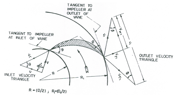
Fig. 27.1. Inlet and outlet velocity triangles for an impeller vane.
(Source: Modi and Seth, 1998)
Let V = absolute velocity of the liquid (measured in the stationary frame of reference),
u = peripheral (tangential) velocity of the impeller (i.e., rotational velocity),
Vr = relative velocity of the liquid (i.e., velocity of the liquid relative to the impeller),
Vf = velocity of flow of the liquid, and
Vw = velocity of whirl of the liquid.
Further, let Θ = impeller vane angle at the inlet, and Φ = impeller vane angle at the outlet. Similarly, α = angle between the absolute velocity of entering liquid and the peripheral velocity of the impeller at the inlet point, and β = angle between the absolute velocity of leaving liquid and the peripheral velocity of the impeller at the outlet (exit) point.
Since there are no guide vanes at the entrance to the impeller, the direction of absolute velocity of liquid at this point is not directly known. However, for the best efficiency of the centrifugal pump, it usually assumed that the liquid enters the impeller radially. Thus, a = 90º (see inlet velocity triangle in Fig. 27.1) and the velocity of whirl (Vw) at the inlet is zero, and hence V and Vf at the inlet are the same. Moreover, it is desired that the liquid enters and leaves the vane without shocks. This can be ensured if the inlet and outlet tips of the vane are parallel to the direction of the relative velocities at the two tips. As such it is assumed that the peripheral velocities u and u1 are parallel to the tangents to the impeller at the inlet and outlet vane tips, respectively (Fig. 27.1). The relative velocity of the liquid (Vr) is obtained by the vector sum of the absolute velocity (V) and the peripheral velocity of the impeller (u).
27.2.4 Minimum Impeller Diameter
An expression for the minimum diameter of an impeller can be derived on the basis of the fact that for the pump to start pumping, the centrifugal head must be equal to the total head or manometric head (Hm). That is,
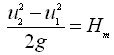 (27.4)
![]()
 (27.5)
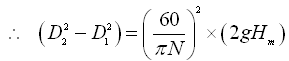
Let’s assume that D1 = 0.5 D2 (as mentioned above). Now, Eqn. (27.5) can be expressed as follows:
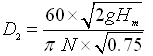 (27.6)
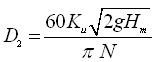
Or, 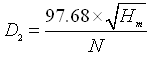 (27.7)
Equation (27.7) will yield the minimum outside diameter of an impeller for given manometric head (Hm) and speed of the pump (N).
27.2.5 Head Generated by the Impeller and Design Discharge
The work done per second by the impeller on the liquid is given as:
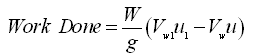 (27.8)
Where, W = weight of the liquid per second passing through the impeller; Vw and Vw1 = velocity of whirl of the liquid at the inlet and outlet of the impeller, respectively; and u and u1 = peripheral velocity of the impeller at its inlet and outlet, respectively.
Since the liquid enters the impeller radially (Fig. 27.1), the value of Vw will be zero. Therefore, Eqn. (27.8) will reduce to:
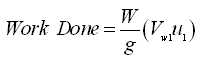 (27.9)
Thus, the work done per second per unit weight of the liquid is  , which represents the theoretical head imparted by the impeller to the liquid (i.e., theoretical manometric head). That is,
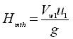 (27.10)
Now, from the inlet velocity triangle (Fig. 27.1), we have and
and  , and therefore,
![]() (27.11)
(27.11)
Similarly, from the outlet velocity triangle (Fig. 27.1), we have 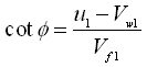 and hence
![]() (27.12)
(27.12)
Where, , and
, and 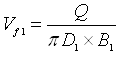 .
.
Now, the design discharge of the pump (Q) can be calculated as follows:
Case 1: If vane thickness is neglected, the design discharge (Q) is given as:
![]() (27.13)
(27.13)
Where, D1 = outer diameter of the impeller, and B1 = width of the impeller vane at the outlet.
Case 2: If the vane thickness of the impeller is considered, then Q is given as:
![]() (27.14)
(27.14)
Where, A1 = percentage of the outlet area not occupied by impeller vanes.
27.3 Design of Suction and Delivery Pipes
27.3.1 Diameter of Suction Pipe
Let ds be the diameter of the suction pipe and Vs be the velocity of flow in the suction pipe. Then, the amount of water to be pumped is given as:
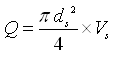 (27.15)
Or,  (27.16)
Here, the value of Vs is usually taken as 1.5 to 3 m/s (Modi and Seth, 1998).
27.3.2 Diameter of Delivery Pipe
Let dd be the diameter of the delivery pipe and Vd be the velocity of flow in the delivery pipe. Then, the discharge of the pump can be given as:
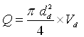 (27.17)
Or,  (27.18)
Here, the value of Vd is generally taken as 1.5 to 3.5 m/s. In fact, the value of Vd is normally equal to or slightly higher than that of Vs (Modi and Seth, 1998).
27.4 Design of Pump Casing
Pumps casing should be so designed as to minimize the loss of kinetic head through eddy formation, friction, etc. Efficiency of a pump largely depends on the type of casing. In general, centrifugal pump casings are of three types: (i) volute casing, (ii) volute casing with vortex chamber, and (iii) diffuser casing. Interested readers are referred to Michael and Khepar (1999) and Lobanoff and Ross (1985) for details about the design of pump casings and other elements.
27.5 Cavitation Problem
A problem commonly encountered in the operation of hydraulic machines is ‘cavitation’. Cavitation occurs when the pressure drops below the vapor pressure of the liquid. It is caused as follows:
(a) Vaporization of the liquid and/or release of dissolved air at low pressure,
(b) Movement of the vapor/gas into a high-pressure region,
(c) Collapse of the vapor/gas bubbles when subjected to a high pressure, and
(d) Release of energy and pressure wave of high intensity (i.e., shock wave) resulting in (i) pitting and erosion of metal surfaces, and (ii) noise and vibration of the machine.
Thus, in brief, cavitation can be defined as the formation and subsequent collapse of vapor bubbles. When these collapses occur violently on interior surfaces of the hydraulic machines (e.g., pumps, turbines, etc.), they produce ring-shaped indentations on the surface called ‘pits’. Continued cavitation and pitting not only deteriorate the efficiency of hydraulic machines but also severely damage the hydraulic machines and hence, it must be avoided.
Cavitation is more likely to take place in hydraulic machines in the places such as: (a) suction side of the pumps, (b) draft tube of the hydraulic turbines, (c) venturi or the minimum area section of passages, (d) boundaries in the vicinity of high velocity flow, and (e) siphon passages. It is necessary to avoid cavitation in hydraulic machines, which can be done by limiting the minimum suction pressure above a critical value which is denoted by the Thoma’s cavitation parameter (sc) and is expressed as follows:
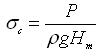 (27.19)
Or, 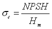 (27.20)
Where, P = local pressure in the hydraulic machine, ρ = density of the fluid, Hm = pumping head, and NPSH = net positive suction head.
Note that the efficiency of a hydraulic machine deteriorates rapidly if the Thoma’s cavitation parameter (σ) is allowed to drop below the critical value (σc). The critical cavitation parameter (σc) is related to the specific speed of hydraulic machines.
It is sometimes preferred to express the cavitation parameter as the suction specific speed (S) instead of σc, which is given as:
 (27.21)
Where, N = speed of the pump, Q = discharge of the pump, and H = total suction head corrected for the local vapor pressure (i.e., NPSH).
The minimum safe value of S for pumps is 3 and that for turbines is 4. The usual design practice is to allow the formation of bubbles but not to allow the collapse of bubbles until downstream of the impeller passage. These are referred to as the supercavitating conditions in flow. Axial flow pumps are generally designed considering the supercavitating principle.
27.6 Net Positive Suction Head
The net positive suction head (NPSH) is defined as the absolute pressure head at the inlet of the pump minus the vapor pressure head (absolute) corresponding to the temperature of the liquid pumped plus the velocity head at this point (Modi and Seth, 1998). That is,
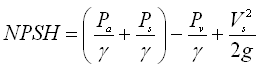 (27.22)
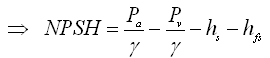 (27.23)
Where, Pa = atmospheric pressure, Pv = vapor pressure of the liquid at the operating temperature, γ = unit weight of the liquid, hs = static suction head, and hfs = friction head losses on the suction side of the pump.
It is clear from Eqn. (27.23) that NPSH is equal to the total suction head (Hs)abs corrected for the local vapor pressure. Thus, the concept of NPSH is applicable to only suction installation of centrifugal pumps.
The concept of NPSH is very commonly used in the pump industry. For any pump installation, a distinction is usually made between the net positive suction head required (NPSHR) and the net positive suction head available (NPSHA). If sufficient energy is not present in the liquid on the intake side of the pump to move the liquid into the eye of the impeller, then the liquid will vaporize and cavitation will occur in the pump. As mentioned above, cavitation should be avoided.
In order to ensure that the required energy is available on the intake side of the pump, an analysis must be made to determine the net positive suction head available (NPSHA). The available head is a function of the system in which the pump operates. It can be calculated for all suction installations of pumps using Eqn. (27.23). Also, the relationship between drawdown and discharge from the water source must be known to compute the NPSHA-Q relationship.
On the other hand, NPSHR varies with the pump design, pump-speed, and its capacity. Its value is determined experimentally for each pump by the pump manufacturers. Manufacturers conduct laboratory tests to determine NPSHR values for each pump model they manufacture. Both the NPSHA and NPSHR vary with the discharge in such a manner that with an increase in the discharge NPSHA decreases but NPSHR increases. In order to have cavitation-free operation of centrifugal pumps, the value of NPSHA should be greater than that of NPSHR. In other words, if NPSHA is less than NPSHR, then the pumps will cavitate.
References
Lobanoff, V.S.L. and Ross, R.R. (1985). Centrifugal Pumps Design and Application. Gulf Publishing Co. Book Division, London.
Michael, A.M. and Khepar, S.D. (1999). Water Well and Pump Engineering. Tata McGraw-Hill Publishing Co. Ltd., New Delhi.
Modi, P.N. and Seth S.M. (1998). Hydraulics and Fluid Mechanics. Twelfth Edition, Standard Book House, New Delhi.
Stepanoff, A.J. (1994). Centrifugal and Axial Pumps: Theory, Design and Application. John Wiley & Sons, New York.
Suggested Readings
Michael, A.M. and Khepar, S.D. (1999). Water Well and Pump Engineering. Tata McGraw-Hill Publishing Co. Ltd., New Delhi.
Lal, J. (1969). Hydraulic Machines. Metropolitan Book Co. (Pvt.) Ltd., Delhi.
Stepanoff, A.J. (1994). Centrifugal and Axial Pumps: Theory, Design and Application. John Wiley & Sons, New York.
Lobanoff, V.S.L. and Ross, R.R. (1985). Centrifugal Pumps Design and Application. Gulf Publishing Co. Book Division, London.
Last modified: Wednesday, 5 February 2014, 4:49 AM