Site pages
Current course
Participants
General
Module 1_Fundamentals of GW
Module 2_Well Hydraulics
Module 3_Design, Installation and Maintenance of W...
Module 4_Groundwater Assessment and Management
Module 5_Principle, Design and Operation of Pumps
Module 6_Performance Characteristics, Selection an...
Keywords
12 April - 18 April
19 April - 25 April
26 April - 2 May
Lesson 25 Pump Installation and Head Calculation
25.1 Installation of Centrifugal Pumps
Efficient operation of a centrifugal pump is based on its proper installation with suitable foundation in correct location and with appropriate alignment of coupling. The type of installation depends on the nature of water source (surface water bodies or groundwater), type of well (open well or tubewell), extent of lining in case of tubewells, seasonal variation in the static water level, and kind of prime mover (electric motor or diesel engine) used in operating the pump. Typical low-lift centrifugal pump installations are of two types (FAO, 1986): (a) suction installation, and (b) sump installation or below ground installation.
25.1.1 Suction Installation
The simplest installation is the suction installation (Fig. 25.1). The suction lift of an ordinary centrifugal pump is limited to 5-6 m in practice, and it is further reduced if a larger length of the suction pipe is used. Hence, a suitable length and larger size of suction pipe is desirable for better performance of the pump. Also, the suction lift reduces to about 2 m at an altitude of 2000 m (FAO, 1986). In case of higher suction lift, it is certain that the problem will be experienced in priming the pump, retaining its prime, etc. A foot valve (Fig. 25.1) is an important part of any such installation, without which the moment the pump stops or slows down, all the water in the pipeline will run back through the pump making it impossible to restart the pump unless the pipeline is first refilled with water. In addition, if the pump is driven by an electric motor and water flows back through the pump; it can run backwards and possibly damage the electrical system.
If the delivery pipeline is long, it is also important to have another check valve (non-return valve) at the pump outlet (Fig. 25.1). This is necessary because if suddenly pump stops, the flow will continue until the pressure drops enough to cause cavitation in the pipeline; when the upward momentum is exhausted, the flow reverses and cavitation bubbles implode creating severe water hammer. In addition, severe water hammer can occur when the flow reverses which causes the instantaneous closure of the foot valve. The impacts of such events are very dangerous; the pump casing and/or pipeline may burst. Thus, a check valve on the discharge line (at the pump outlet) protects the pump from any such back surge down the pipeline.
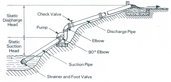
Fig. 25.1. Suction installation of a centrifugal pump. (Source: FAO, 1986)
25.1.2 Sump Installation
The other installation of centrifugal pumps could be below the ground surface as shown in Fig. 25.2; it is also known as ‘sump installation’. If there is no surface mounting position low enough to permit suction pumping, centrifugal pumps are often placed in a sump or a pit where the suction head will be small or where the pump is located below the water level (Fig. 25.2). In the situation shown in Fig. 25.2, a long shaft is used to drive the pump from a surface mounted electric motor. Such a positioning of prime mover protects the motor and electric equipment from any possible flood, i.e., maximum water level in surface water bodies.
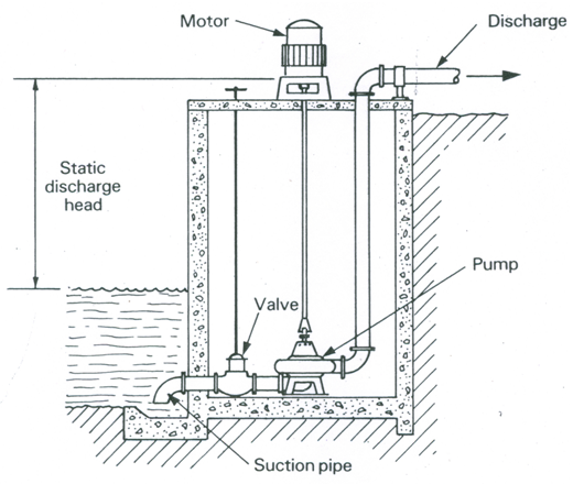
Fig. 25.2. Sump installation of a centrifugal pump. (Source: FAO, 1986)
25.2 Operation of Centrifugal Pumps
The basic principle on which a centrifugal pump functions has been discussed in Lesson 24. The first step in the operation of a pump is priming, i.e., the suction pipe and the pump-casing are filled with water so that no air/air-pocket is left. Now, when the pump is started, the revolution of the impeller inside a casing full of water produces a forced vortex, which is responsible for imparting a centrifugal head to the water. The rotation of the impeller causes a reduction in pressure at the center due to which the water in the suction pipe rushes into the eye of the pump. The speed of the pump should be high enough to produce centrifugal head sufficient to initiate discharge against the delivery head.
Mechanical action of the pump is to impart a velocity to the water. A water particle with a given velocity will rise to the same vertical height through which any particle should fall freely under gravity in order to attain the same velocity starting from rest. Therefore,
![]() (25.1)
(25.1)
Thus, if the outlet velocity of water in a pump is V, the pump can theoretically deliver water against a head of ![]() .
.
25.3 Limitation of Suction Lift
The absolute pressure head at the inlet of the pump is expressed as follows:
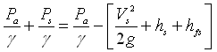 (25.2)
Where, Pa = atmospheric pressure acting on the free liquid surface in the sump, Ps = gage pressure at the inlet of the pump, γ= unit weight of water, Vs = velocity of flow in the suction pipe, ![]() = suction velocity head, hs = suction lift (static suction head), and hfs = friction head losses in the suction pipe and in the foot valve and strainer.
= suction velocity head, hs = suction lift (static suction head), and hfs = friction head losses in the suction pipe and in the foot valve and strainer.
It is not possible to create an absolute pressure at the pump inlet lower than the vapor pressure of the liquid. Thus, if Pv = vapor pressure of the liquid in the absolute unit, then in the limiting case, Pa + Ps = Pv, and hence from Eqn. (25.2), the limiting value of the suction lift (hsl) can be given as follows:
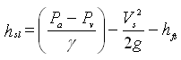 (25.3)
Note that the value of the suction lift (hs) should not be more than that given by Eqn. (25.3). This is because greater hs may result in a rapid vaporization of the liquid due to the reduction in pressure, which may ultimately lead to the incidence of cavitation that must be avoided for proper operation of the pump.
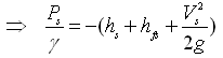
25.4 Calculation of Total Head
The energy imparted by a pump to the liquid increases pressure which is reflected as increased head. Total head generated by a pump is called ‘pumping head’ which is also known as ‘manometric head’ or ‘total dynamic head’. Fig. 25.3 illustrates how the manometric head of a centrifugal pump can be calculated using the basic law of energy conservation. For this, let’s consider five points 0, 1, 2, 3 and 4 in a pumping system as shown in Fig. 25.3. The pumping head mainly comprise suction head and delivery head. Hence, the expressions for the suction head (Hs), delivery head (Hd), and manometric head (Hm) of a centrifugal pump are derived in the subsequent sub-sections.
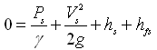
25.4.1 Suction Head
Applying the Bernoulli’s equation between Points 0 (at the water surface in the sump) and 1 (at the centerline of the pump or at the pump inlet) and considering water surface in the sump (i.e., Point 0) as a datum, we have:
 (25.4)
 (25.5a)
 = Total suction head (25.5b)
Fig. 25.3. Heads of a centrifugal pump. (Source: Modi and Seth, 1998)
25.4.2 Delivery Head
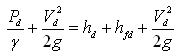
Similarly, applying the Bernoulli’s equation between Points 3 (at the pump outlet) and 4 (at the water surface in delivery tank) and considering Point 3 as a datum, we have:
 (25.6)
![]() (25.7a)
(25.7a)
![]() (25.7b)
(25.7b)
Where, Pd = gage pressure at the outlet of the pump, Vd = velocity of flow in the delivery pipe,![]() = delivery velocity head, hd = static delivery head, hfd = friction head losses in the delivery pipe, and the remaining symbols have the same meaning as defined earlier. Note that the ‘total delivery head’ (Hd) is given as:
= delivery velocity head, hd = static delivery head, hfd = friction head losses in the delivery pipe, and the remaining symbols have the same meaning as defined earlier. Note that the ‘total delivery head’ (Hd) is given as:
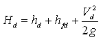 (25.8)
25.4.3 Manometric Head
‘Manometric head’ of a pump is the total head produced by the pump to satisfy specific external requirements. If there are no energy losses in the impeller and casing of the pump (valid in an ideal or theoretical situation only), the manometric head will be equal to the energy given to the liquid by the impeller. As we know from the velocity triangles of an impeller, the energy (in terms of head) given to the liquid by the impeller is ![]() . However, in reality, head losses occur inside the pump (i.e., in the impeller and casing), and therefore the manometric head (Hm) for practical purposes is given as:
. However, in reality, head losses occur inside the pump (i.e., in the impeller and casing), and therefore the manometric head (Hm) for practical purposes is given as:
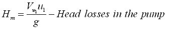 (25.9a)
Or, 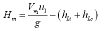 (25.9b)
Where, Vw1 = velocity of whirl of the liquid at the impeller outlet, u1 = peripheral velocity of the impeller at the outlet, hLi = head loss in the impeller, and hLc = head loss in the casing.
Now, applying the Bernoulli’s equation between Points 1 and 3, and considering Point 1 as a datum, we have:
Pressure head at Point 1 + Velocity head at Point 1 + Head generated by the impeller = Pressure head at Point 3 + Velocity head at Point 3 + Difference in
the levels of two gages + Head losses in the pump
That is,
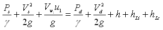 (25.10)
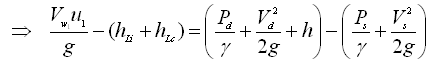 (25.11)
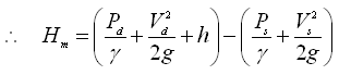 (25.12)
Thus, the manometric head (Hm) is equal to the difference between total energy of the liquid at outlet of the pump and that at inlet of the pump. In the above equations, Pd = pressure at the outlet of the pump (i.e., pressure gage reading on the delivery pipe); Ps = pressure at the inlet of the pump (i.e., vacuum gage reading on the suction pipe); h = vertical difference in the levels of the vacuum and pressure gages; Vd = velocity of flow in the delivery pipe; and Vs = velocity of flow in the suction pipe.
If the two gages are fitted at the same level, then h = 0, and hence Eqn. (25.12) reduces to:
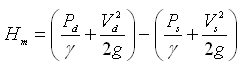 (25.13)
Now, substituting the expressions of ![]() [from Eqn. (25.7a)] and
[from Eqn. (25.7a)] and ![]() [from Eqn. (25.5a)] in Eqn. (25.13), we have another expression of the manometric head (Hm) as follows:
[from Eqn. (25.5a)] in Eqn. (25.13), we have another expression of the manometric head (Hm) as follows:
 (25.14)
Equation (25.14) is the commonly used expression to compute manometric head (or pumping head) required for a given pumping system. Note that one external parameter which does not appear in Eqn. (25.14) is the operating head that is needed for operating sprinklers, gated pipe or drip irrigation systems. Therefore, for computing the total head which a pump must provide to operate an irrigation device, it is necessary to add the required operating head.
In practice, the total dynamic head (TDH) for the suction installation of a centrifugal pump (Fig. 25.1) is calculated as follows:
TDH = Discharge Gage Reading + Vacuum Gage Reading + Distance between Point of Attachment of the Vacuum Gage and Centerline of the Discharge Gage +  (25.15)
However, in case of sump installation, the centrifugal pump is installed in such a way that there is a positive pressure on the suction side. In this situation, a pressure gage is used on the pump suction instead of a vacuum gage. Thus, for the sump installation of a centrifugal pump (Fig. 25.2), TDH is calculated as follows:
TDH = Discharge Gage Reading - Suction Gage Reading + Distance between Centerlines of Discharge and Suction Gages +  (25.16)
25.5 Calculation of Friction Head Losses
As we know that there is a frictional resistance offered to the liquid flowing through suction and delivery pipes, which results in the loss of head. Head losses due to friction are known as friction head losses, which constitute significant components of the total pumping head for a particular pumping system. Friction head losses are classified as: (a) major friction head losses, and (b) minor friction head losses. Major friction head losses are defined as the friction head losses due to the roughness of the inner surface of pipe-network, and the viscosity and density of the flowing fluid. Minor friction head losses are defined as the head losses due to pipe fittings, bends, entry and exit, sudden expansion and contraction, valves, screen, and so on.
The major friction head losses (hf) in the suction and delivery pipes of a pumping system can be calculated by the Darcy-Weisbach equation, which is given as:
 (25.17)
Where, f = friction factor (its value is usually obtained from the Moody diagram), L = length of the pipe, v = velocity of flow, d = inside diameter of the pipe, and g = acceleration due to gravity.
Moreover, minor friction head losses can be calculated with the help of standard tables. The sum of major and minor friction head losses constitutes the ‘total friction head losses’. Generally, the value of major friction head losses is much higher than that of minor friction head losses, and hence the minor friction head losses are often neglected while computing the total head of a pumping system (i.e., TDH). However, if the value of minor friction head losses is significantly large, they must not be neglected during the calculation of pumping head (TDH).
References
-
FAO (1986). Water Lifting Devices. FAO Irrigation and Drainage Paper 43, Food and Agriculture Organization of the United Nations, Rome, Italy.
-
Modi, P.N. and Seth S.M. (1998). Hydraulics and Fluid Mechanics. Twelfth Edition, Standard Book House, New Delhi.
Suggested Readings
-
Michael, A.M. and Khepar, S.D. (1999). Water Well and Pump Engineering. Tata McGraw-Hill Publishing Co. Ltd., New Delhi.
-
Murty, V.V.N. and Jha, M.K. (2011). Land and Water Management Engineering. Sixth Edition, Kalyani Publishers, Ludhiana.
-
James, L.G. (1988). Principles of Farm Irrigation System Design. John Wiley & Sons, New York.
QUIZ
State whether the following statements are true (T) or false (F):
- The suction lift of an ordinary centrifugal pump is practically limited to 10 m.
- At the pump inlet, an absolute pressure lower than the vapor pressure of the liquid to be pumped can be created.
- Larger suction head in centrifugal pumps may lead to cavitation.
- The theoretical manometric head of a centrifugal pump is equal to the energy given to the liquid by the impeller.
- Both major and minor friction head losses can be calculated by the Darcy-Weisbach formula.
- The total head required for operating a sprinkler irrigation system is equal to the manometric head of the pump plus the operating head of the sprinkler.
Last modified: Friday, 14 March 2014, 11:53 AM