Site pages
Current course
Participants
General
Module 1_Fundamentals of GW
Module 2_Well Hydraulics
Module 3_Design, Installation and Maintenance of W...
Module 4_Groundwater Assessment and Management
Module 5_Principle, Design and Operation of Pumps
Module 6_Performance Characteristics, Selection an...
Keywords
12 April - 18 April
19 April - 25 April
26 April - 2 May
Lesson 29 Rotodynamic Pumps for Special Purposes
In this lesson, rotodynamic pumps which are used for special purposes are discussed. Such pumps are: propeller pumps, mixed-flow pumps, submersible pumps, vertical turbine pumps, and jet pumps. In addition, self-priming devices for rotodynamic pumps are succinctly discussed.
29.1 Propeller Pump
An axial flow pump or propeller pump propels water by the reaction to lift forces produced by rotating its blades. This action both pushes the water past the rotor or impeller and also imparts a spin to the water which if left uncorrected would represent wasted energy, since it will increase the friction and turbulence without helping the flow of water down the pipe. Axial flow pumps therefore usually have fixed guide vanes, which are angled so as to straighten the flow and convert the spin component of velocity into extra pressure, in much the same way as with a diffuser in a centrifugal pump.
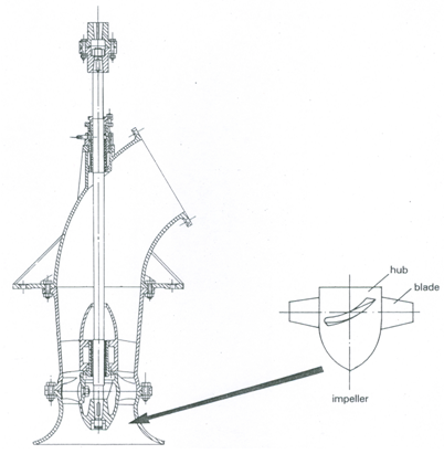
Fig. 29.1. Axial flow or propeller pump. (Source: FAO, 1986)
Figure 29.1 shows a typical axial flow pump of this kind, in which the guide vanes, just above the impeller, also serve a second structural purpose of housing a large plain bearing, which positions the shaft centrally (FAO, 1986). This bearing is usually water lubricated and has features in common with the stern gear of an inboard-engined motor boat.
Axial flow pumps are generally manufactured to handle flows ranging from 150 to 1500 m3/h for vertically mounted applications, usually with heads in the range of 1.5 to 3.0 m. By adding additional stages (i.e., two or more impellers on the same shaft) extra lift up to 10 m or so can be obtained (FAO, 1986).
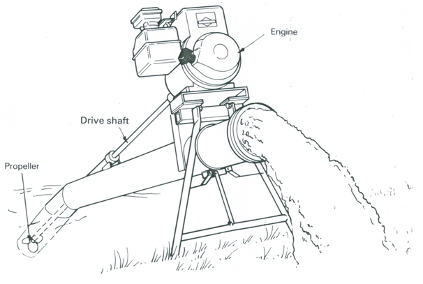
Fig. 29.2. Portable axial flow pump (IRRI model). (Source: FAO, 1986)
Since axial flow pumps are designed for very large flows at low heads, normally concrete pipes are used to avoid the high cost of large-diameter steel pipes. They are generally used in canal irrigation schemes where large volumes of water are to be lifted 2-3 m, typically from a main canal to a feeder canal.
Small-scale propeller pumps are usually locally manufactured such as the portable axial flow pump (Fig. 29.2) developed by the International Rice Research Institute (IRRI), Philippines. It is designed to deliver up to 180 m3/h at heads in the range of 1 to 4 m. This pump requires a 5 hp diesel engine or electric motor capable of driving its shaft at 3000 rpm; its length is 3.7 m, the discharge tube is 150 mm in diameter and the overall weight without the prime mover is 45 kg (FAO, 1986).
29.2 Mixed-Flow Pump
The mixed-flow pump, as its name suggests, involves something of both axial and centrifugal pumps. In the irrigation context, it can often represent a useful compromise to avoid the limited lift of an axial flow pump, but still achieve higher efficiency and larger flow rates than an ordinary centrifugal pump. Also, axial flow pumps generally cannot sustain any suction lift, but mixed-flow pumps can, although they are not self-priming. Figure 29.3 shows a surface mounted suction mixed-flow pump and its installation. Here, the swirl imparted by the rotation of the impeller is recovered by delivering the water into a snail-shell volute or diffuser (identical in principle to that of a centrifugal volute pump).
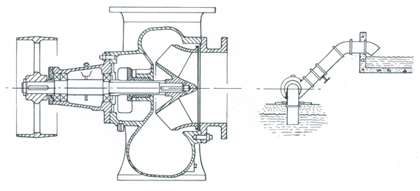
Fig. 29.3. Surface mounted mixed-flow pump. (Source: FAO, 1986)
An alternative arrangement somewhat similar to an axial flow pump is shown in Fig. 29.4, which is known as a submersible mixed-flow pump. In this case, a ‘bowl’ casing is used so that the flow spreads radially through the impeller and then converges axially through fixed guide vanes which remove the swirl and thereby add to the efficiency. Pumps of this kind are installed submerged, which avoids the priming problems that can afflict large surface suction rotodynamic pumps such as in Fig. 29.3. The ‘bowl mixed-flow pump’ is sometimes called a turbine pump, and it is actually equivalent to the centrifugal turbine pump described later in this lesson. In the ‘bowl mixed-flow pump’, the passage through the rotor reduces in cross-section and thereby accelerates water and imparts energy to it, while the fixed guide vanes are designed as a diffuser to convert kinetic energy into pressure energy and thereby increase both pumping head and efficiency. Two or more ‘bowl mixed-flow pumps’ can also be stacked on the same shaft to make a multi-stage turbine pump; such pumps are commonly used as borehole pumps because of their long narrow configuration. Bowl mixed-flow pumps typically operate with discharges from 200 to 12000 m3/h over heads from 2 to 10 m. Their multiple stage versions are often used at heads of up to about 40 m (FAO, 1986).
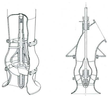
Fig. 29.4. Submerged mixed-flow pump. (Source: FAO, 1986)
29.3 Submersible Pump
Where high heads are needed, the primary means to achieve this with a single impeller centrifugal pump are either to increase the impeller speed or to increase impeller diameter. However, there are practical limits to this way of increasing head. Therefore, in practice either single impeller pumps are connected in series or a more practical solution is to use a specially designed pump (commonly known as submersible pump) wherein multiple (two or more) impellers mounted on the same shaft such that the output from one impeller feeds directly through suitable passages in the casing to the next impeller. Submersible pumps have the motor and the bowl assembly as a unit submerged below the lowest pumping water level (Fig. 29.5). A water-proof cable supplies power to the motor. Submersible pumps to fit inside 10, 15, 20 and 25 cm borewells are available in India. They can be used for discharges varying from 40 to 3000 L/min and heads varying from 15 to 150 m (Raghunath, 2007). They can be installed in crooked wells but the repair to motor or pump requires its removal from the well, and hence the motor or pump is subject to abrasion by sand.
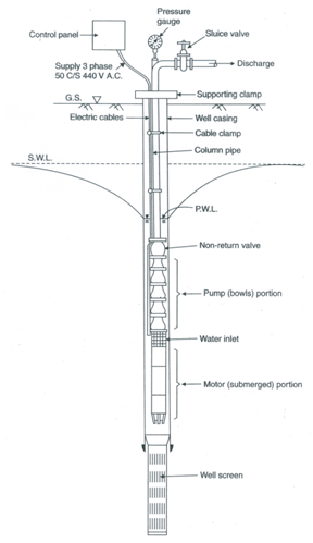
Fig. 29.5. Schematic diagram of a submersible pump.
(Source: Raghunath, 2007)
Submersible pumps have the advantage that they can be installed in the localities where there is little or no floor space to install a pump unit as well as in the localities where noise or theft is a serious issue. They can be either water or oil lubricated. The new types of voltage regulated starters have solved the problem of overloading. Although the initial costs of submersible pumps are lower than those of vertical turbine pumps, their repair and maintenance costs are higher.
29.4 Vertical Turbine Pump
Vertical turbine pumps are most widely used for large deep tubewells. The bowl-assembly (containing impellers) is placed below the lowest pumping water level, but the prime mover (electric motor or diesel engine) is placed on the ground surface and is connected by a long shaft (Fig. 29.6). Usually deep-well turbine pumps are used for fairly high flows under high heads. The overall efficiency of vertical turbine pumps ranges from 50 to 80% (Raghunath, 2007).
Vertical turbine pumps have the advantages of high efficiency, high head pumping capability and excellent serviceability. Their impellers can be of semi-open or fully enclosed types. However, they have some serious disadvantages. They require sufficiently straight and plumb well for installation and proper operation and are subject to abrasion by sand. The maintenance problem becomes severe when they are pumping corrosive water unless the pump, column pipe, line shaft and other components are made of non-corrosive materials. Also, the lubrication and vertical alignment of line shaft is critical.
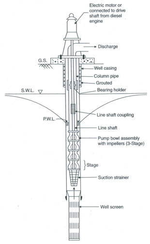
Fig. 29.6. Schematic diagram of a vertical turbine pump.
(Source: Raghunath, 2007)
29.5 Jet Pump
A jet pump consists of a centrifugal pump and a jet assembly (Fig. 29.7) and it is essentially a self-priming centrifugal pump which is based on the fact that if water is accelerated through a jet, it causes a drop in pressure. In the jet pump, the pump is fitted into a secondary casing which contains water at the discharge pressure. A proportion of the water from this chamber is bled back to a nozzle fitted into the suction end of the pump casing and directed into the eye of the impeller (Fig. 29.7). If the pump has been used once (having been manually
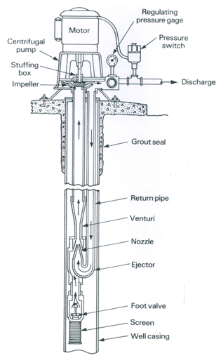
Fig. 29.7. Schematic diagram of a borehole jet pump. (Source: FAO, 1986)
primed initially), it remains full of water so that on start up the water is re-circulated from the delivery side of the pump to the bottom of the suction pipe and is injected through a nozzle to impart additional kinetic energy. Thus, the jet causes low pressure in the suction line and thereby increases suction considerably compared to the effect of impeller on its own, which in turn provides additional suction lift. Initially, the entrapped air is gradually drawn up the suction line. As soon as all the air is removed from the system, most of the discharge goes up the discharge line and a small proportion is fed back into the nozzle. In this way, the jet pump not only creates a higher suction lift than normal but also it can reliably run on ‘snore’ (i.e., sucking a mixture of air and water without losing its prime). This makes it useful in situations where shallow water is to be pumped under suction and it is difficult to obtain sufficient submergence of the foot valve, or where a water source may occasionally be pumped dry. The provision of a jet assembly allows a surface-mounted pump and motor to ‘suck’ water from depths of about 10 to 20 m; the diffuser after the jet raises the pressure in the rising main and avoids cavitation (FAO, 1986).
Jet pumps are often viable for pumping fairly small discharges (40-90 L/min) under low heads (15 to 45 m) when the water level is more than 7.6 m from the ground surface (Raghunath, 2007). Their capacity reduces as the lift increases. They are generally used for residential buildings and hotels. Jet pumps are of two types: twin type for the borewells of 15 cm diameter and larger, and packer type (duplex) for the borewells of less than 15 cm diameter (Raghunath, 2007). Although the jet circuit usually needs 1.5 to 2 times the flow being delivered (discharge), and therefore is a source of significant power loss, the jet pumps are sometimes useful for lifting sandy or muddy water as they are not so easily clogged as an ordinary submerged pump. In such cases, however, a settling tank is provided on the ground surface between the pump suction and the jet pump discharge to allow the pump to draw clear water.
Moreover, jet pumps have two main disadvantages (FAO, 1986): (i) greater complexity and hence higher cost, and (ii) reduced efficiency because power is used in pumping water through the jet, though some of this power is recovered by the pumping effect of the jet. Considering these disadvantages of jet pumps, it is better to use a conventional centrifugal pump in the situations where there is little or no suction lift. However, in the situations where suction pumping is essential, a jet pump can offer a successful solution.
29.6 Self-priming Devices for Rotodynamic Pumps
Rotodynamic pumps will start pumping only if their impellers are flooded with water prior to start up. Obviously, the easiest way is to submerge the pump in the water source, but this is not always possible or convenient (e.g., portable pump sets). If sufficient water is present in the pump casing, then even if the suction pipe is empty, suction will be created and water can be lifted. A variety of methods are used to fill rotodynamic pumps with water when they are placed above the water level. It is important, however, to note that if the suction line is empty but the delivery line is full, it is necessary to drain the delivery line so as to remove the back pressure on the pump and enable it to be primed. Otherwise, it will be difficult, if not impossible, to flush out the air in the system.
The most basic method of priming is to use a foot valve to retain water in the system. In this case, the system has to be filled initially by pouring water into the pipes using a bucket and then it is hoped that the foot valve will retain water in the system even after the pump is not used for some time. In many cases, however, foot valves leak, especially if mud or grit is present in the water and settles between the valve and its seat when it attempts to close (FAO, 1986).
The two most common methods for priming surface-mounted and engine-driven suction centrifugal pumps are either by using an ordinary hand pump or a diaphragm pump on the delivery line. For example, Fig. 29.8 illustrates a hand-operated diaphragm pump fitted on the delivery side of a portable centrifugal pump for priming.
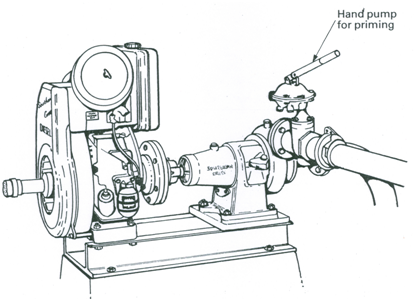
Fig. 29.8. Direct-coupled air-cooled diesel engine and centrifugal pump with a diaphragm pump for priming. (Source: FAO, 1986)
Several alternative methods of priming surface suction pumps can be designed using a large water container/tank with appropriate accessories to suitably fill the pump and suction line with water and maintain water in the tank for the next start. Yet another simple method to use, but only if the delivery line is long enough to carry a sufficient supply of water, is to fit a hand valve immediately after the pump discharge (instead of a non-return valve) so that when the pump is turned off, the valve can be manually closed. Then, the opening of this valve will refill the pump from the delivery line to ensure that it is flooded on restarting. Besides these simple and cost-effective self-priming devices, sometimes the most reliable arrangement is to use a special ‘self-priming centrifugal pump’ which has an enlarged upper casing with a baffle in it (FAO, 1986). Additionally, the jet pump (discussed in the previous section) is a special type of self-priming centrifugal pump.
References
FAO (1986). Water Lifting Devices. FAO Irrigation and Drainage Paper 43, Food and Agriculture Organization of the United Nations, Rome, Italy.
Raghunath, H.M. (2007). Ground Water. Third Edition, New Age International Publishers, New Delhi.
Suggested Readings
Michael, A.M. and Khepar, S.D. (1999). Water Well and Pump Engineering. Tata McGraw-Hill Publishing Co. Ltd., New Delhi.
Murty, V.V.N. and Jha, M.K. (2011). Land and Water Management Engineering. Sixth Edition, Kalyani Publishers, Ludhiana.
Jensen, M.E. (Editor) (1980). Design and Operation of Farm Irrigation Systems. ASAE Monograph No. 3, ASAE, St. Joseph, Mi.
Lal, J. (1969). Hydraulic Machines. Metropolitan Book Co. (Pvt.) Ltd., Delhi.
Last modified: Wednesday, 5 February 2014, 4:59 AM