Site pages
Current course
Participants
General
Module 1_Fundamentals of GW
Module 2_Well Hydraulics
Module 3_Design, Installation and Maintenance of W...
Module 4_Groundwater Assessment and Management
Module 5_Principle, Design and Operation of Pumps
Module 6_Performance Characteristics, Selection an...
Keywords
12 April - 18 April
19 April - 25 April
26 April - 2 May
Lesson 30 Affinity Laws
30.1 Introduction
In this lesson, affinity laws and their utility are discussed. As we know that the total head, discharge and power of a centrifugal pump are related to the size and speed of its impeller. Changing the size or speed of an impeller significantly affects the operational characteristics of a centrifugal pump. Therefore, such knowledge allows the pump manufacturers and/or users to modify the performance of a single pump so as to match the system need or understand the pump performance under different operating conditions.
The mathematical relationships of total head, discharge and power with the pump speed and with the impeller diameter are known as affinity laws. Thus, two types of affinity laws each consisting of a set of three equations exist, which are discussed in subsequent sections.
30.2 Effect of Changes in Pump Speed on the Pump Performance
Most pump manufacturers have standardized the speed for which they publish characteristic curves. Belt driven electric pumps or engine-driven pumps can operate at a range of speeds, which can be varied by suitable adjustments. Variation in the pump speed can be used advantageously to operate a single pump to match two different system head curves or to provide two different design discharges. Reduction in the pump speed is also one of the best ways to rectify surging pumps (Jensen, 1980). However, the selection of a proper pump which can operate efficiently at two different speeds enhances the complexity of pump selection several fold.
Total dynamic head (or total head), discharge and power of a pump are related to the speed of an impeller (i.e., pump speed). These relations can be developed by using fundamental equations of pumps. As we know, the peripheral velocity of the impeller (u) is given as:
 (30.1)
![]()
Where, D = diameter of the impeller, and N = speed of the impeller or pump.
From the velocity triangles, it becomes evident that if u changes to u’ (vane angles remaining constant), then the flow velocity (V) is related as:
![]()
![]()
Now, the pump discharge Q = Area across flow × w, which suggests that:
![]()
![]()
That is, the pump discharge varies linearly with a change in the pump speed.
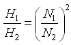
Moreover, from the fundamental equation of pumps, it is clear that the total head (H) depends on the squares of velocities, which are directly proportional to the pump speed (N). That is,![]() . In addition, the power required for a pump (P) is directly proportional to Q × H. PαN3 Therefore,.
. In addition, the power required for a pump (P) is directly proportional to Q × H. PαN3 Therefore,.
Thus, if N1 and N2 are the two pump speeds, and Q1, Q2; H1, H2 and P1, P2 are respectively discharges, heads and powers corresponding to the two pump speeds N1 and N2, we obtain three equations relating the discharge, head and power with the pump speed as follows:
 (30.2)
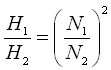 (30.3)
and 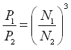 (30.4)
The above three equations are known as Affinity Law I, which suggests that the discharge varies linearly with a change in the speed, the head varies as the square of the ratio of the two speeds, and the power varies as the cube of the ratio of the two speeds. Thus, a slight increase in the pump speed will deliver more water at a higher head, but will require considerably more power to drive the pump.
30.3 Effect of Changes in Impeller Diameter on the Pump Performance
As mentioned earlier, the discharge of a pump can be changed by modifying either its speed or the diameter of its impeller which changes the pump’s performance. The former is normally not possible because the speed of the driving motor is fixed. Therefore, the outer diameter of the impeller (D) has to be enlarged or reduced according as H or Q is to be increased or decreased. We can reduce the outer diameter of the impeller by trimming. By fixing rings to the shroud of an impeller, we can increase the outer diameter and extend the impeller blades to the required size, though it is not a usual practice. The effect of the alteration of D is two fold. Firstly, the alteration of D changes peripheral velocity (u) without changing N. Therefore, from Eqn. (30.1) we have:
![]()
![]()
Secondly, the alteration of D changes discharge (Q). Since Q = A α V, because the area across flow (A) will remain constant. Further, head (H) depends on u2, V2, etc. and hence, V2 α D2, thereby we have:
H2 α D2
In addition, the power required for a pump (P) is directly proportional to Q × H. Therefore,P α D3 .
Thus, similar to the impact of change in pump speed on pump performance, we obtain three equations which relate the impact of change in impeller diameter to changes in pump performance. If D1 and D2 are the two impeller diameters, and Q1, Q2; H1, H2 and P1, P2 are respectively discharges, heads and powers corresponding to the impeller diameters D1 and D2, the three equations relating the discharge, head and power with the impeller diameter are as follows:
 (30.5)
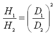 (30.6)
and 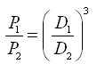 (30.7)
The above three equations are known as Affinity Law II, which suggests that the discharge varies linearly with a change in the impeller diameter, the head varies as the square of the ratio of the two impeller diameters, and the power varies as the cube of the ratio of the two impeller diameters.
Note that the applicability of the Affinity Law II is limited to less than 20% changes in the original outer diameter of the impeller (James, 1988).
On the whole, it is worth mentioning that all of the above relationships [Eqns. (30.2) to (30.7)] are approximate because leakage, windage, and bearing losses have been neglected. Nevertheless, they are very useful for the pump manufacturers because the main characteristics of a new pump (i.e., modified pump) can be determined without testing it in the laboratory.
30.4 Illustrative Example
Problem: A centrifugal pump requires 5 kW power when it runs at 1450 rpm and delivers water against a head of 10 m. If the pump is operated at 1750 rpm, calculate the head developed and the power required by the pump.
Solution: From the question, N1 = 1450 rpm, N2 = 1750 rpm, H1 = 10 m, and P1 = 5 kW. The head developed by the pump (H2) and the power required (P2) at 1750 rpm can be calculated by using the Affinity Law I.
From the Affinity Law I, we have:
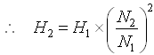
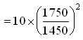
= 14.57 m, Ans.
Also, from the Affinity Law I we have:

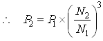
= 8.79 kW, Ans.
References
James, L.G. (1988). Principles of Farm Irrigation System Design. John Wiley & Sons, New York.
Jensen, M.E. (Editor) (1980). Design and Operation of Farm Irrigation Systems. ASAE Monograph No. 3, ASAE, St. Joseph, Mi.
Suggested Readings
Michael, A.M. and Khepar, S.D. (1999). Water Well and Pump Engineering. Tata McGraw-Hill Publishing Co. Ltd., New Delhi.
Murty, V.V.N. and Jha, M.K. (2011). Land and Water Management Engineering. Sixth Edition, Kalyani Publishers, Ludhiana.
Jensen, M.E. (Editor) (1980). Design and Operation of Farm Irrigation Systems. ASAE Monograph No. 3, ASAE, St. Joseph, Mi.
James, L.G. (1988). Principles of Farm Irrigation System Design. John Wiley & Sons, New York.
Last modified: Wednesday, 5 February 2014, 5:00 AM