Site pages
Current course
Participants
General
Module 1_Fundamentals of GW
Module 2_Well Hydraulics
Module 3_Design, Installation and Maintenance of W...
Module 4_Groundwater Assessment and Management
Module 5_Principle, Design and Operation of Pumps
Module 6_Performance Characteristics, Selection an...
Keywords
12 April - 18 April
19 April - 25 April
26 April - 2 May
Lesson 31 Selection of Suitable Pumps
31.1 Introduction
A variety of pumps (centrifugal and other types) and their different models are manufactured by a large number of manufacturers in almost every country. These pumps are available in a wide range of sizes and have widely varying characteristics. Therefore, a proper selection of pump for a given purpose is necessary. A properly selected pump not only effectively meet the desired water demand but also operates efficiently, thereby enhancing its service life and minimizing OMR (operation, maintenance and replacement) costs. The information required for selecting a suitable pump is: (i) total head of the pumping system (system head curve), (ii) design discharge, and (iii) pump characteristic curves. The system head curve and design discharge are discussed in the subsequent sections, and the pump characteristic curves are discussed in Lesson 28.
In this lesson, although general criteria for pump selection are described, the focus is on the selection of centrifugal pumps. The selection and operating characteristics of other types of pumps (e.g., vertical turbine pump, submersible pump, propeller pump, mixed-flow pump, and jet pump) are discussed in Michael and Khepar (1999).
31.2 System Head Curve
System head curve (Fig. 31.1) is a relationship between total head and discharge for a given pumping system and it illustrates how the total head varies with an increase in discharge. It essentially describes the head-discharge (H-Q) requirements of a pumping system. It indicates that the more head is required to increase flow (discharge) through the system.
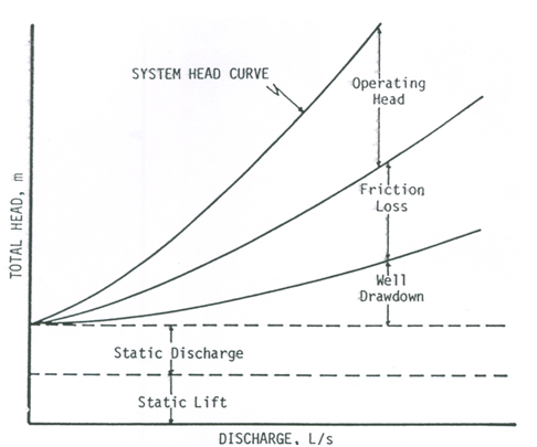
Fig. 31.1. A typical ‘system head curve’ with its different components. (Source: Jensen, 1980)
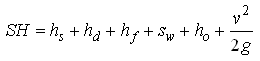
System head curves are developed by computing the total head required by a pumping system to deliver different discharges. The following equation, which shows different head components contributing to the system head curve, is used to calculate system head (SH) or total head for a pumping system:
 (31.1)
Where, hs = static suction head, hd = static delivery head, hf = friction head losses (major and minor), sw = drawdown in the sump (water source) during pumping, ho = operating head, and ![]() = velocity head.
= velocity head.
For some systems, not all of the above-mentioned head components would be applicable. In the above equation, the static suction head or static lift (hs) and static delivery head or static discharge head (hd) are independent of the system flow (Q), whereas the remaining head components increase as the discharge increases (Fig. 31.1). The system head (SH) is independent of the pump, with the exception of friction losses occurring in the column pipe a vertical turbine pump (Jensen, 1980). Note that the system head curve is time dependent because of temporal variations in the well drawdown, friction, operating conditions, and the static water level of the water source. Also, the static delivery head (hd) may be time dependent. The system head curve is useful for determining the operating point of a pump to be installed; it is discussed in Section 31.4.
31.3 Determination of Design Discharge
The discharge of a pump that meets the peak demand of water in a domestic, irrigation or industrial sector is known as design discharge of the pump. If the source of water is groundwater, the safe yield of a well becomes the dominating factor in deciding the design discharge. In this case, if the maximum water requirement per day during peak periods is less than the safe yield of the well, the peak water demand will be the design discharge. Conversely, if the peak water demand is more than the safe yield of the well, the water requirement during peak periods should be adjusted to be equal to the safe well yield in order to ensure efficient utilization of available groundwater. This adjustment could be done by supplying part of the peak demand from other wells or surface-water sources. On the other hand, if the source of water is surface water (e.g., river, lake, pond, or canal) and there is no constraint on the availability of water, the design discharge of the pump (i.e., pump capacity) can be determined based on the peak water requirement. An example of this situation is presented below considering the requirement of a pump for irrigating crops grown by a farmer or a group of farmers.
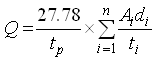
The discharge of the pump used for irrigation should meet the peak demand of water for a given cropping pattern. The rate of pumping (pump discharge) depends on the area under different crops, water requirements of the crops, irrigation interval and the duration of pump operation in a day. Hence, the design discharge or capacity of an irrigation pump can be calculated as (Michael and Khepar, 1999):
 (31.2)
Where, Q = design discharge of the pump (L/s); Ai = area under the ith crop (ha); di = depth of irrigation for the ith crop (cm); ti = irrigation interval (day); and tp= duration of pumping (h/day).
31.4 Criteria for Pump Selection
31.4.1 General Criteria
Proper selection of a pump requires the knowledge and use of the pump characteristic curves and the system head curve. The normal procedure for selecting a pump is to first determine the system head curve and desired discharge (design discharge). Thereafter, the pump manufacturer’s catalogs having characteristics curves or tables are used to select a couple of pump models for consideration which can operate efficiently at or near the design discharge.
Engineers, pump installers and irrigation equipment salesmen have historically determined the design discharge and the system’s total head for that discharge (Jensen, 1980). These values are used to select a pump. In practice, very few irrigation or drainage systems will have fixed operating conditions. Therefore, by determining the system head curve or curves for a range of discharges above and below the design discharge, sufficient information will be available to evaluate pump performance for all expected operating conditions. Thus, by matching the system head curve or curves for a range of discharges with the characteristic curves of various models of pumps, the pump that can provide maximum efficiency can be selected. Alternatively, if the pump characteristics are reported in a tabular form, the pump that requires minimum power to operate at the design head and design capacity can be selected after comparing the pump characteristics data from several reputed pump manufacturers (Michael and Khepar, 1999).
31.4.2 Criteria for Centrifugal Pump Selection
The selection criteria described in the pervious section in applicable for centrifugal pumps also. Some additional points are to be taken care of. Trimming of the impellers to match the pump to the specific use is quite common. The decisions that must be made for centrifugal pump selections are: which model of pump to use, how much to trim the impeller, and what speed to turn the impeller. Manufacturer’s characteristic curves contain information required to make these decisions (Jensen, 1980). It is also necessary to determine the size of prime mover (motor or engine) required to drive the pump.
Centrifugal pumps have a suction and discharge fitting or flange. The pump is connected with standard pipe fittings to both suction and discharge pipes. Care should be taken to minimize friction losses on the suction side. Large friction losses can cause cavitation which must be avoided. Most centrifugal pumps used for irrigation require that a foot valve be installed on the intake end of the suction pipe in order to ensure that the pump could remain primed at all times. There are some self-priming centrifugal pumps as discussed in Lesson 29, which may be selected according to the need and budget.
31.4.3 Operating Point of a Pump
A system characteristic between the head required (H) and the discharge (Q) to be maintained is generally expressed as a parabolic equation as follows (Jensen, 1980; FAO, 1986):
![]() (31.3)
(31.3)
Where, K1 and K2 are constants for the system. Equation (31.3) is graphically illustrated in Fig. 31.1.
A centrifugal pump usually operates at different combinations of head and discharge given by its head-discharge (H-Q) characteristic curve. The particular H-Q combination at which a pump operates is known as the ‘pump’s operating point’. A system head curve and the H-Q characteristic curve of the pump are used to determine the operating point. The point of intersection of the pump’s H-Q characteristic curve and the system characteristic (H-Q) curve locates the actual operating point of a pump when it will be installed in a given system (Fig. 31.2). At the operating point, the head and discharge (H-Q) requirements of a system are equal to the head and discharge (H-Q) generated by the pump.
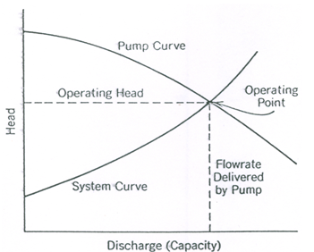
Fig. 31.2. Superposition of ‘system head curve’ and ‘pump head-discharge curve’ for determining operating point. (Source: James, 1988)
Once the operating point of a pump is determined, the power, overall efficiency, and NPSHR (net positive suction head required) for the pump can be obtained (Fig. 31.3).
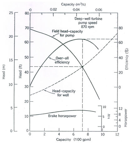
Fig. 31.3. Typical system and pump head-capacity curves.
(Source: Schwab et al., 2005)
31.5 Selection of Type of Pump
The relative merits and applicability of different types of pumps are discussed in earlier lessons. Volute centrifugal pumps are adapted to a wide range of head-discharge conditions compared to vertical turbine pumps and propeller pumps. The efficiency of vertical turbine pumps, submersible pumps and propeller pumps drops rapidly when applied under conditions different from those for which they have been designed (Michael and Khepar, 1999). The suitability of commonly used irrigation pumps to specific pumping situations is presented in Table 31.1, which can be used as guidelines for selecting a suitable pump type.
Table 31.1. Suitability of common types of irrigation pumps to specific pumping applications (Source: Michael and Khepar, 1999)
|
Sl. No. |
Source of Water |
Lift |
Yield |
Suitable Pump Type |
Remarks |
|
1 |
Stream/Canal |
<2.5 m |
High |
Propeller pump |
Volute centrifugal pumps inefficient at low heads |
|
2 |
Stream/Canal |
3-12 m |
High |
Mixed-flow pump |
Volute centrifugal pumps also provide satisfactory efficiency at heads> 6 m. Tractor-operated pumps feasible upto about 6 m lift |
|
3 |
Stream/Canal |
>12 m |
Medium to High |
Volute Centrifugal Pump |
Multi-stage pumps to be preferred for high beads |
|
4 |
Shallow Open Well |
3-6 m |
Medium |
Mixed-Flow Pump or Volute Centrifugal pump |
Pump located at ground surface |
|
5 |
Deep Open Well (Electricity available) |
>6 m |
Medium |
Volute Centrifugal Pump directly coupled to Electric Motor |
Pumping set located close to water table in well |
|
6 |
Deep Open Well (Electricity not available) |
>6 m |
Medium |
Volute Centrifugal Pump driven by Diesel Engine |
Engine located at or near ground level, pump driven through belt/shaft |
|
7 |
Deep Open Well (Electricity not available) |
>6 m |
Low |
Jet Pump coupled to Diesel Engine |
Pumping set located at ground surface |
|
7 |
Sewage Pumping |
<6 m |
Medium |
Non-clog Centrifugal Pump coupled to Electric Motor/Engine |
Pumping set located at ground surface |
|
8 |
Shallow Tube-well or Filter Point |
<6 m |
Medium |
Volute Centrifugal Pump |
Pump driven by electric motor or diesel engine located at the ground surface |
|
9 |
Shallow Tube-well |
5-15 m |
Medium |
Volute Centrifugal Pump installed in sump within suction and water table limits |
In case of engine drive, the pump is located in the sump, but the engine is placed on the ground surface. |
|
10 |
Deep Tubewell (Electricity available) |
>15 m |
Medium/High |
Submersible Pump or Vertical Turbine Pump |
Assured service facility essential, especially in case of submersible pumps. |
|
11 |
Deep Tubewell (Electricity not available) |
>15 m |
Medium/High |
Deep Well Turbine Pump |
Engine located on the ground surface |
|
12 |
Pumping from Sump or Drainage Pumping |
<6 m |
High |
(i) Propeller Pump for lifts < 2.5 m (ii) Mixed-Flow Pump for lifts > 2.5 m |
Motor-driven pumps to be provided with a float-controlled automatic switch |
|
13 |
Canal Lifts |
<15 m |
High |
Mixed-Flow Pump |
To lift the flow of a canal from a lower elevation to a higher elevation |
References
-
FAO (1986). Water Lifting Devices. FAO Irrigation and Drainage Paper 43, Food and Agriculture Organization of the United Nations, Rome, Italy.
-
James, L.G. (1988). Principles of Farm Irrigation System Design. John Wiley & Sons, New York.
-
Jensen, M.E. (Editor) (1980). Design and Operation of Farm Irrigation Systems. ASAE Monograph No. 3, ASAE, St. Joseph, Mi.
-
Michael, A.M. and Khepar, S.D. (1999). Water Well and Pump Engineering. Tata McGraw-Hill Publishing Co. Ltd., New Delhi.
-
Schwab, G.O., Fangmeier, D.D., Elliot, W.J. and Frevert, R.K. (2005). Soil and Water Conservation Engineering. Fourth Edition, John Wiley and Sons (Asia) Pte. Ltd., Singapore.
Suggested Readings
-
Michael, A.M. and Khepar, S.D. (1999). Water Well and Pump Engineering. Tata McGraw-Hill Publishing Co. Ltd., New Delhi.
-
Murty, V.V.N. and Jha, M.K. (2011). Land and Water Management Engineering. Sixth Edition, Kalyani Publishers, Ludhiana.
-
Jensen, M.E. (Editor) (1980). Design and Operation of Farm Irrigation Systems. ASAE Monograph No. 3, ASAE, St. Joseph, Mi.
-
Schwab, G.O., Fangmeier, D.D., Elliot, W.J. and Frevert, R.K. (2005). Soil and Water Conservation Engineering. Fourth Edition, John Wiley and Sons (Asia) Pte. Ltd., Singapore.
-
James, L.G. (1988). Principles of Farm Irrigation System Design. John Wiley & Sons, New York.
Last modified: Friday, 14 March 2014, 12:03 PM