Site pages
Current course
Participants
General
MODULE 1. Analysis of Statically Determinate Beams
MODULE 2. Analysis of Statically Indeterminate Beams
MODULE 3. Columns and Struts
MODULE 4. Riveted and Welded Connections
MODULE 5. Stability Analysis of Gravity Dams
Keywords
5 April - 11 April
12 April - 18 April
19 April - 25 April
26 April - 2 May
LESSON 2. Axial Force, Shear Force and Bending Moment in Beam
2.1 Introduction
To start with, consider a simply supported beam subjected to some arbitrary external load as shown in Figure 2.1a. Let the beam is cut by a section mn. Figure 2.1b shows the free body diagram of the portion of the beam to the left part of the section mn. Fin represents the internal force on section mn. Now using the concept of equivalent force-couple system, Fin may be represented by a force Fc applied at the centroid of the cross-section and a couple Mx as shown in Figure 2.1c. The force Fc may further be decomposed into two orthogonal components, Fx, normal to the plane of the cross-section and Vx, tangential to the plane of the cross-section (see Figure 2.1d).
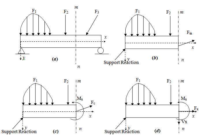
Fig. 2.1.
Similarly the internal force on any section may be represented by three quantities Fx, Vx and Mx called respectively as axial force, shear force and bending moment.
Sign Convention
Throughout the syllabus we will consistently use the following sign convention.
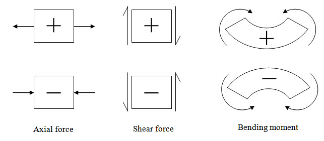
Fig. 2.2.
2.2 Computation of Support Reaction and Internal Forces
The following procedure may be followed in order to determine the support reaction of a beam.
(a) Draw the free body diagram of the entire structure. In this free body diagram only unknowns are the support reaction.
(b) Apply the static equilibrium condition to determine the unknowns.
The following procedure may be followed in order to determine the internal forces at any section of a beam.
At the desired location take a section which cut the beam into two parts.
Isolate any part and draw the free body diagram. In this diagram only unknowns are the internal forces.
Apply the static equilibrium conditions to determine the internal forces.
This is demonstrated via the following example.
Example 1
A simply supported beam AB is subjected to a concentrated load P as shown in Figure 2.3. Calculate reactions at A and B. Calculate shear force and bending moment at a distance x from A.
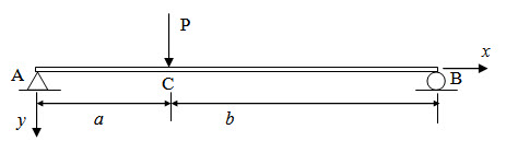
Fig. 2.3.
Calculation of support reactions
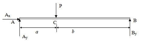
Fig. 2.4.
Figure 2.4 shows the free body diagram of the entire structure. Here support reactions Ax, Ay and By are unknowns. Now applying the static equilibrium conditions we have,
\[\sum {{F_x}}=0 \Rightarrow {A_x}=0\] (2.1)
\[\sum {{F_y}}=0 \Rightarrow {A_y} + {A_y} - P=0 \Rightarrow {A_y} + {A_y}=P\] (2.2)
\[\sum {{M_B}}=0 \Rightarrow {A_y}(a + b) - Pb=0 \Rightarrow {A_y}={{Pb} \over {\left( {a + b} \right)}}\] (2.3)
Substituting in equation (2.2) we have,
\[{B_y}={{Pa} \over {\left( {a + b} \right)}}\] (2.4)
Calculation of shear force and bending moment
Two sections viz. and are considered. Corresponding free body diagrams are shown in Figure 2.5.
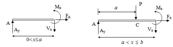 Fig. 2.5.
For 0 < x ≤ a
\[\sum {{F_x}}=0 \Rightarrow {F_x}=0\] (2.4)
\[\sum {{F_y}}=0 \Rightarrow {A_y} - {V_x}=0 \Rightarrow {V_x}={{Pb} \over {\left( {a + b} \right)}}\] (2.5)
\[\sum {{M_B}}=0 \Rightarrow {A_y}x - {M_x} = 0 \Rightarrow {M_x}={{Pb} \over {\left( {a + b} \right)}}x\] (2.6)
For a ≤ x < b
\[\sum {{F_x}}=0 \Rightarrow {F_x}=0\] (2.7)
\[\sum {{F_y}}= 0 \Rightarrow {A_y} - P - {V_x} = 0 \Rightarrow {V_x}= - {{Pa} \over {\left( {a + b} \right)}}\] (2.8)
\[\sum {{M_B}}=0 \Rightarrow {A_y}x - P(x - a) - {M_x}=0 \Rightarrow {M_x} = Pa\left( {1 - {x \over {a + b}}} \right)\] (2.9)
2.3 Bending Moment and Shear Force Diagram
Shear force and bending moment diagrams are the graphical representation of variation of shear force and bending moment respectively along the axis of the beam. For illustration consider the previous example where the variation of shear force and bending moment may be summarized as,
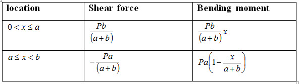
Corresponding diagrams are shown in Figure 2.6.
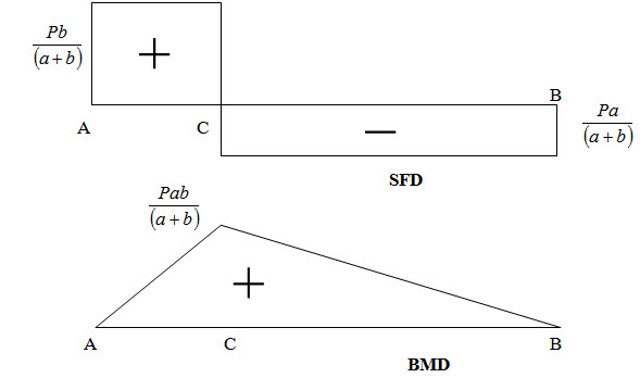
Fig. 2.6.
Example 2
A simply supported beam AB is subjected to a uniformly distributed load of intensity of q as shown in Figure 2.7. Calculate support reactions and draw shear force and bending moment diagram..
Fig. 2.7.
Solution
The free body diagram of the entire structure is shown in Figure 4.2.
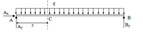
Fig. 2.8.
Applying equilibrium conditions we have,
\[\sum {{F_x}}=0 \Rightarrow {A_x}=0\]
\[\sum {{M_B}}=0 \Rightarrow {A_y}l - ql{l \over 2}=0 \Rightarrow {A_y}={{ql} \over 2}\]
\[\sum {{F_y}}=0 \Rightarrow {A_y} + {B_y} - ql = 0 \Rightarrow {B_y}={{ql} \over 2}\]
Take a section at C which is at a distance x from A. Figure 2.9 shows the free body diagram of the portion of the beam to the left part of the section.
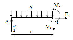
Fig. 2.9.
Taking force equilibrium in vertical direction, we have,
\[\sum {{F_y}}=0 \Rightarrow {{ql} \over 2} - qx - {V_x} = 0 \Rightarrow {V_x}=qx - {{ql} \over 2}\] (2.10)
Taking moment about C we have,
\[\sum {{M_C}}=0 \Rightarrow {{ql} \over 2}x - qx{x \over 2} - {M_x}=0 \Rightarrow {M_x}={{ql} \over 2}x - {{q{x^2}} \over 2}\] (2.11)
Shear force and bending moment diagram (graphical representations of equations (2.10) and (2.11)) are shown in Figure 2.10.
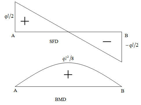
Fig. 2.10.
Suggested Readings
Hbbeler, R. C. (2002). Structural Analysis, Pearson Education (Singapore) Pte. Ltd.,Delhi.
Jain, A.K., Punmia, B.C., Jain, A.K., (2004). Theory of Structures. Twelfth Edition, Laxmi Publications.
Menon, D., (2008), Structural Analysis, Narosa Publishing House Pvt. Ltd., New Delhi.
Hsieh, Y.Y., (1987), Elementry Theory of Structures , Third Ddition, Prentrice Hall..
Last modified: Monday, 16 September 2013, 9:38 AM