Site pages
Current course
Participants
General
Module 1. Hydraulic Basics
Module 2. Hydraulic Systems
MODULE 3.
MODULE 4.
MODULE 5.
MODULE 6.
MODULE 7.
MODULE 8.
19 April - 25 April
26 April - 2 May
LESSON 10. Strainers and Filters
10.1 Introduction
The oils used in hydraulic systems contain foreign matter in solid and liquid forms, which is quite undesirable and need to be removed. Hence, strainers, filters, and magnetic plugs are used to remove dust particles or foreign matter from a hydraulic fluid and are effective as safeguards against contamination. It is very important to select a filter that will improve the reliability of a lubrication or hydraulic system by eliminating failure due to contamination of oil used in the system. Maintaining hydraulic fluid within the allowable limits is quite difficult to protect the equipment. Therefore it is necessary to prevent the contamination in the fluid and also remove the contaminants if present in the fluid. Hence filters are installed at suitable places in the hydraulic system.The filtration devices used in the system are commonly known as strainer and filters.
10.2 Strainers
To remove large particles of foreign matter from a hydraulic fluid a strainer is provided as the primary filtering system. Its screening action is not as good as that of a filter but a strainer offers less resistance to flow of the fluid. A strainer usually consists of a metal frame wrapped with a fine-mesh wire screen or a screening element made up of varying thicknesses of specially processed wire. Strainers are used in the pump inlet lines. There may be different possible arrangements of strainer for use in a pump inlet line. If one strainer causes excessive friction in the flow of fluid to the pump, two or more strainers can be used in parallel.
10.3 Filters
Filters are generally provided to remove the small foreign particles from a hydraulic fluid and are most effective in removing fine contaminants. Filters can be classified based upon (i) location and (ii) full/partial filtering action. Based upon location filters can be classified as inlet line filters, pressure line filters and return line filters. Based upon filtering action filters are classified as full-flow filters and proportional-flow filters.
10.3.1 Inlet Line Filters
Inlet filters for pipe-lines and systems are designed to stop dust and dirt particles from entering the pump and contaminating the oil. Replaceable elements are available as disposable, cleanable. Inlet line filters must cause low pressure drop or the pump will not be able to lift the oil from the tank. Therefore inlet line filters are coarse filters. Fig. 10.1 shows the location of inlet line filter.
Fig. 10.1:Inlet Line Filter Location Sketch
10.3.2 Pressure Line Filter
This type of filters is used to protect downstream components such as valves and actuators from contamination. Since these are sized for the output of the pump, pressure filters tend to be smaller than return line filters. In systems using accumulators, pressure filters must be sized according to the large effective flow rates.In some applications, pressure filters are used as isolation filters to protect specific components. These filters are non-bypass type of filters which are capable of withstanding full system differential pressure.
Fig. 10.2: Pressure Line Filter Location Sketch
10.3.3 Return Line Filters
Return flow filters usually have cartridge elements in an in-line mounted housing within the reservoir itself which is also called as an in-tank filter. Return line filters are an integral part of an effective contamination control system. Return line filters are ideal for systems where the pump is the sensitive component. These are placed before the fluid enters the reservoir in order to prevent debris and particles from recirculation through the system.
Fig. 10.3: Return Line Filter Location Sketch
10.3.4 Full-flow Filter
A full flow filter is designed to filter the full output from pump. In this type of filter the fluid entering a unit passes through a filtering element. A full-flow type of filter provides a more positive filtering and offers greater resistance to flow, particularly when it becomes dirty. A hydraulic liquid enters a full-flow filter through an inlet port in the body and flows around an element inside a bowl.
Filtering occurs as a liquid passes through the element and into a hollow core, leaving the dirt and impurities on the outside of the element. A filtered liquid then flows from a hollow core to an outlet port and into the system.
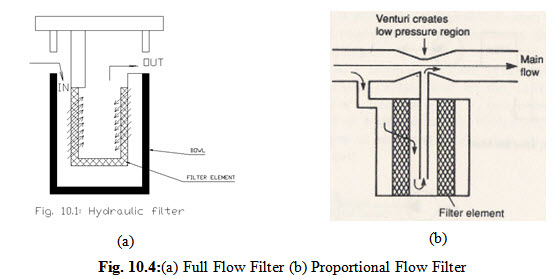
10.3.5 Proportional-flow Filter
In this type of filter there is a venturi tube. The throat of venturihas smaller diameter which increases the velocity of fluid moving through it . Flow through a venturi throat causes a pressure drop at the narrowest point. This pressure drop causes a sort of suctionthat draws a portion of a fluid down around a cartridge through a filter element and up into the venturi throat. This method has the advantage of low pressure drop.
10.4 Contamination Indicators
The effectiveness of the filter can be checked by a contamination indicator. The contamination of a filter is measured by the drop in pressure. As the contamination increases, the pressure ahead of the filter rises. This pressure acts on a spring-loaded piston. As the pressure increases, the piston is pushed against the spring and is displayed onto a display unit.
10.5 Contaminants
There may be following types contaminates which may be there in the hydraulic fluids-
-
Biological materials like straw shreds, hair, flies, etc.
-
Welding scales
-
Bits of sealing materials
-
Wear particles
-
Rust particles
-
Water
-
Dirt from atmosphere
-
New oil
Last modified: Saturday, 15 March 2014, 5:54 AM