Site pages
Current course
Participants
General
Module 1. Hydraulic Basics
Module 2. Hydraulic Systems
MODULE 3.
MODULE 4.
MODULE 5.
MODULE 6.
MODULE 7.
MODULE 8.
19 April - 25 April
26 April - 2 May
LESSON 15. Volume Meters
15.1 Introduction
The working of hydraulic systems depends upon the flow rate and pressure of the oil in various sections of the circuit. Flow causes motion and increased rate of flow results in higher velocities of hydraulic cylinders or motors. Measurement of oil flow rate is important for controlling the speed of actuators in hydraulic systems. Further, higher flow rates may cause turbulent flow in the system leading to increased energy loss through friction and premature wear due to cavitation. Thus measurement of flow rate or velocity is of prime importance in hydraulic systems. In hydraulic systems, which use incompressible oil as the medium, volumetric flow is used to measure flow rate. A common type of inflow meter used for measuring volumetric flow rate is shown in Fig. 15.1.
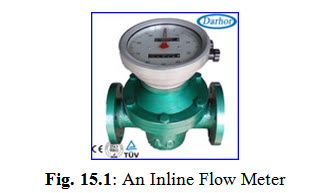
(Courtesy: http://www.alibaba.com/showroom/diesel-oil-volume-meter.html)
Flow measurement may be expressed in units of rate of flow such as Litre Per Minute (LPM) or cubic meter per second (m3/s) etc. It may also be expressed in terms of total quantity in litre or cubic meter.
15.2 Volume Meters
There are different types of flow meters depending upon the application. Choice of a flow meter depends upon the flow quantities, flow rates, and types of liquids involved. Flow meters must be used only for the purpose for which they were made. Some common methods used for measuring flow rate are discussed below.
15.2.1 Venturi / Orifice Meters
The traditional method of measuring flow is based upon Bernoulli’s equation which was discussed in lesson 2. The flow velocity of the fluid in pipe is increased locally by introducing a restriction as shown in Fig. 15.2.
Add sktch
(a) (b)
Fig. 15.2: (a) Venturi Meter (b) Orifice Meter
The obstruction may be in the form of a venturi or an orifice plate. This increases flow velocity causing a pressure drop, the pressure being minimum where the cross section of the fluid stream is minimum. The differential pressure across points 1 and 2 is then a measure of the flow velocity or flow rate.
15.2.2 Variable Area Flowmeter
Variable area flowmeters, also known as rotameters, uses a float in a vertical tube of variable cross-sectional area as shown in Fig. 15.3
Fig. 15.3: Rotameter
Add sktch
The obstruction in the path of fluid due to float causes increase in the fluid velocity which results in a differential pressure drop across the float. Due to this, an upward force acts on the float. The upward force is a function of the flow rate. The weight of the float acts downwards. If the upward force due to differential pressure drop is more than the weight, the float rises above, otherwise the float moves down. When the float moves up, the area around the float increases. This increase in area decreases pressure drop across the float and hence the upward force. The float therefore settles at a vertical position where the weight of the float balances the upward force due to differential pressure. The vertical position of the float thus gives the flow rate of the fluid.
15.2.3 Turbine Flowmeter
A turbine flowmeter uses a turbine mounted in a pipe to measure the flow rate of the fluid in the pipe as shown in Fig. 15.4.
Fig. 15.4: Turbine Flow Meter
Add sktch
The flowing fluid makes the turbine propeller to rotate. The rotational speed of the propeller is proportional to the flow rate. Blade rotation can be counted by a proximity sensor which generates electric pulses. Thus turbine flow meter can be used for remote indication of flow rate.
Last modified: Saturday, 15 March 2014, 10:03 AM