Site pages
Current course
Participants
General
Module 1. Introduction to by-products and waste ge...
Module 2. Waste management concepts
Module 3. Direct combustion of solid waste
Module 4. Thermo-chemical conversion of solid waste
Module 5. Bio-chemical conversion of solid waste
Module 6. Solid waste management
Module 7. Effluent treatment and disposal
Module 8. Presence of typical chemicals
19 April - 25 April
26 April - 2 May
Lesson 11.
Whenever agricultural produce in any form, is handled, processed, packaged and stored, waste water is always generated. The waste water is much polluted and is to be treated depending upon its degree of pollution. It may be only preliminary treatment or preliminary treatment followed by primary treatment or further carried on to secondary treatment or even a complete treatment which include preliminary, secondary and tertiary treatment. The cost for treating waste water lies in its specific characteristics and standards for discharging either into water bodies or municipal waste water treatment plant.
Physical forces as well as chemical and biological processes drive the treatment of wastewater. Treatment methods that rely on physical forces are called unit operations. These include screening, sedimentation, filtration, or flotation. Treatment methods based on chemical and biological processes are called unit processes. Chemical unit processes include disinfection, adsorption, or precipitation. Biological unit processes involve microbial activity, which is responsible for organic matter degradation and removal of nutrients.
Waste water treatment comprises the following four steps:
-
Preliminary treatment: The objective of this operation is to remove debris and coarse materials that may clog equipment in the plant.
-
Primary treatment: Treatment is brought about by physical processe (unit operations) such as screening and sedimentation.
-
Secondary treatment: Biological (e.g. activated sludge, trickling filter, oxidation ponds) and chemical (e.g. disinfection) unit processes are used to treat wastewater. Nutrient removal also generally occurs during secondary treatment of wastewater.
-
Tertiary or advanced treatment: Unit operations and chemical unit processes are used to further remove BOD, nutrients, pathogens and parasites and sometimes toxic substances.
Preliminary Treatment
It consists mainly in separating floating materials, heavy settleable inorganic solids, rags, pieces of wood, oil and greases etc. These coarse material may clog the equipment of plant. The total removal of these materials may reduce the BOD by 15 to 25%. Different operations such as screening, grit chamber/detritious tank, skimming tank may be required for removing these products. The screens used could be vibrating, rotary or static type. Usually screens used have from 10mm down to 1mm opening materials of small size can be removed by high speed circular vibrating polishing screens. Screening systems may be used in combination to maximize the efficiency of the process. The efficiencies of these systems are variable. Rotary drum and discs shows removal percentage of suspended solids upto 40-50%.
Primary treatment
Primary treatment of waste water is done to remove large suspended organic solids. It can be done by sedimentation or screening. Sometimes preliminary treatment is also taken as part of primary treatment. It can be aided by sedimentation tank, coagulation tank and flocculation etc. It allows for the 30% and 60% removal of COD and total suspended solids respectively.
Sedimentation tank
The sedimentation process is mainly based on the concept of that organic matter present in waste water is having specific gravity greater than one. When waste water is made to store for hours, these material will settle down. This is the principle behind sedimentation and accordingly settling velocity is decided; being governed by Stoke’s law
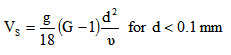
It is applicable for viscous flow and small sized particles, represented by Reynold No. < 0.5
VS = Velocity of settlement of particle in m/sec
d = diameter of particle in meter
\[\upsilon \] = Kinematic viscosity of water
G = Specific gravity of particle
Sedimentation tanks have been used to treat waste water for millennia. Sedimentation is often used in the primary stage in modern waste water treatment plant, reducing the content of suspended solids as well as the pollutant embedded in the suspended solids. Due to the large amount of reagent necessary to treat domestic waste water, preliminary chemical coagulation and flocculation are generally not used, remaining suspended solids being reduced by following stages of the system. However, coagulation and flocculation can be used for building a compact treatment plant (also called a “package treatment plant”), or for further polishing of the treated water.
In Acivated Sludge Treatment process, flocs being created through biological activity are collected in sedimentation tanks, generally referred to as Secondary Clarifiers or Secondary Sedimentation Tanks. Sedimentation tanks can be different shapes, often rectangular or circular. They are sized in order to have an optimal sedimentation speed. If the sedimentation speed is too high, most particles will not have sufficient time to settle, and will be carried with the treated water. If the speed is too low, the tanks will be of an excessive size. As turbulence is a damaging factor leading settled particles to go back in suspension, several devices are used to ensure a quiet flow, such as carefully designed water inlet with baffles.
Sedimentation may be made efficient by the use of stacks of flat pieces that slope slightly upwards in the direction of flow, called lamellar separators. They are parallel and separated by a small distance. These structures work in two ways:
They provide a very large surface area onto which particles may fall and become stabilized.
Because flow is temporarily accelerated between the plates and then immediately slows down, this helps to aggregate very fine particles that can settle as the flow exits the plates.
The use of lamellar separators may allow the use of a smaller sedimentation tank and may enable finer particles to be separated. Typically such structures are used for difficult-to-treat waters, especially those containing colloidal materials.
Features of sedimentation design
Inlets to a settling tank are designed to dissipate the inlet velocity, to distribute the flow uniformly, and to prevent short circuiting. The inlet and outlet channels are designed for a minimum velocity of 2 feet per second at the average flow rate and will have corners filleted to prevent deposition and collection of solids. The following table shows the dimensions of rectangular and circular tanks.
|
Clarifier length or diameter, ft |
Minimum liquid depth, ft |
Sludge blanket depth, ft |
Minimum total depth, ft |
|
Rectangular upto 50 ft length |
6 |
2 |
8 |
|
50 – 100 |
6-7 |
2 |
8-9 |
|
100 – 150 |
7-8 |
3 |
10-11 |
|
150 – 200 |
8-9 |
4 |
12-13 |
|
Circular upto 50 ft diameter |
7 |
2 |
9 |
|
50 – 100 |
7-8 |
2 |
9 |
|
100 – 150 |
8-9 |
3 |
11-12 |
|
150 – 200 |
9-10 |
4 |
13-14 |
Rectangular tanks
The minimum length of flow from inlet to outlet of a rectangular tank is 10 feet in order to prevent short circuiting of flow in the tank. In existing installations, tank length-to-width ratio varies between 3:1 to 5:1. Tanks are designed with a minimum depth of 7 feet except final tanks in activated sludge plants, which are designed with a 9 foot minimum depth.
Inlets and outlets
Inlets to rectangular tanks are designed to prevent channelling of waste water in the tank. Submerged ports, uniformly spaced in the inlet channel, are an effective means of securing distribution without deposition or channelling. Outlet overflow weirs used in rectangular tanks are of the adjustable type, and serrated weirs are preferred over straight ones. Overflow weirs are used in most cases.
Collection and removal of scum and sludge
Means for the collection and removal of scum and sludge are required for all settling tanks. The removal of scum from the tank take place immediately ahead of the outlet weirs, and the equipment may be automatic or manual in operation. Provisions are made so that the scum may be discharged to a separate well or sump so that it can be either sent to the digester or disposed of separately. Rectangular tanks will be provided with scum troughs with the crest about 1 inch above maximum water surface elevation. For small installation (less than 1.0 million gallons per day), hand-tilt troughs consisting of a horizontal, slotted pipe that can be rotated by a lever or screw can be used. Proven mechanical scum removal devices such as chain-and-flight types may be used for larger installation. To minimize the accumulation of sludge film on the sides of the sludge hoppers, a side slope of at least 1.5 vertical to 1 horizontal is used. Separate sludge wells, into which sludge is deposited from the sludge hoppers and from which the sludge is pumped, are preferable to direct pump connections with the hoppers.
Secondary sedimentation
The final step in the secondary treatment stage is to settle out the biological floc or filter material through a secondary clarifier and to produce sewage water containing low levels of organic material and suspended matter.
Flocculation
Flocculation, in the field of chemistry, is a process wherein colloids come out of suspension in the form of floc or flakes by the addition of a clarifying agent. The action differs from precipitation in that, prior to flocculation, colloids are merely suspended in a liquid and not actually dissolved in a solution. In the flocculated system, there is no formation of a cake, since all the flocs are in the suspension.
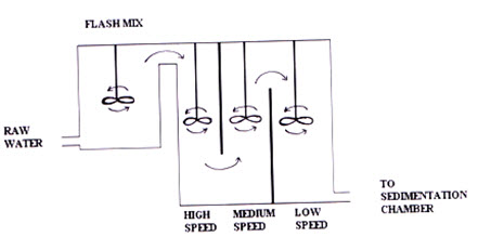
In theory and at the chemical level, coagulation and flocculation is a three step process, consisting of flash mixing, coagulation and flocculation. However, in practice in the treatment plant, there are only two steps in the coagulation/flocculation process – the water first flows into the flash mix chamber, and then enters the flocculation basin.
In the flash mixer, coagulant chemicals are added to the water and the water is mixed quickly and violently. The purpose of this step is to evenly distribute the chemicals through the water. Flash mixing typically lasts a minute or less. If the water is mixed for less than thirty seconds, then the chemicals will not be properly mixed into the water. However, if the water is mixed for more than sixty seconds, then the mixer blades will shear the newly forming floc back into small particles.
After flash mixing, coagulation occurs. During coagulation, the coagulant chemicals neutralize the electrical charges of the fine particles in the water, allowing the particles to come closer together and form large clumps.

The final step is flocculation. During flocculation, a process of gentle mixing brings the fine particles formed by coagulation into contact with each other. Flocculation typically lasts for about thirty to forty-five minutes. The flocculation basin often has a number of compartments with decreasing mixing speeds as the water advances through the basin. This compartmentalized chamber allows increasingly large floc to form without being broken apart by the mixing blades.
Floc
The end product of a well-regulated coagulation/flocculation process is water in which the majority of the turbidity has been collected into floc, clumps of bacteria and particulate impurities that have come together and formed a cluster. The floc will then settle out in the sedimentation basin, with remaining floc being removed in the filter. The best floc size is 0.1 to 3 mm. Larger floc does not settle as well and is more subject to breakup in the flocculation basin. Smaller floc also may not settle.
Flotation
Floatation aims at the removal of fine suspended particles whose separation by sedimentation is practically infeasible as it would require very long treatment times. In general, particles with specific gravity less than unity tend to float spontaneously (e.g., as in the case of skimming); on the other hand, floatation of particles that are only marginally heavier than water can be assisted by introducing fine air bubbles in the liquid. In this case, the bubbles attach to the particulate matter and the buoyant force of the combined particle and gas bubbles is great enough to bring the particle to the surface.
There are three distinct methods to introduce the gas into the liquid as follows:
-
Dissolved air floatation: Air is dissolved in the liquid under a pressure of several atmospheres which is released and the air is then liberated in the form of fine bubbles 40-70 micrometers. This is the most common method used in wastewater treatment.
-
Air floatation: In this case, air is introduced directly to the liquid through diffusers or revolving impellers.
-
Vacuum flotation: It consists of saturating the liquid with air followed by the application of partial vacuum which causes the dissolved air to come out of the solution as fine bubbles.
-
Electrolytic floatation: It is based on the formation of oxygen and hydrogen bubbles from water electrolysis.
Regardless of how air is dissolved in the liquid phase, removal efficiency can be enhanced with the addition of various chemicals such as aluminum and iron salts. These tend to increase and/or alter the particle surface, thus facilitating bubble attachment.
Last modified: Thursday, 30 January 2014, 6:10 AM