Site pages
Current course
Participants
General
MODULE 1.
MODULE 2.
MODULE 3.
MODULE 4.
MODULE 5.
MODULE 6.
MODULE 7.
MODULE 8.
MODULE 9.
MODULE 10.
LESSON 8. DESIGN OF KNUCKLE JOINT
8.1 Introduction
Knuckle joint is used to connect two rods subjected to axial tensile loads. It may also be used to support the compressive load if the joint is guided. It is not suitable to connect rotating shafts which transmit torque. Axes of the shafts to be joined should lie in the same plane and may coincide or intersect. Its construction permits limited relative angular movement between rods, about the axis of the pin. Knuckle joint is widely used to connect valve rod and eccentric rod, in the link of a cycle chain, levers, tie rod joint for roof truss and many other links.
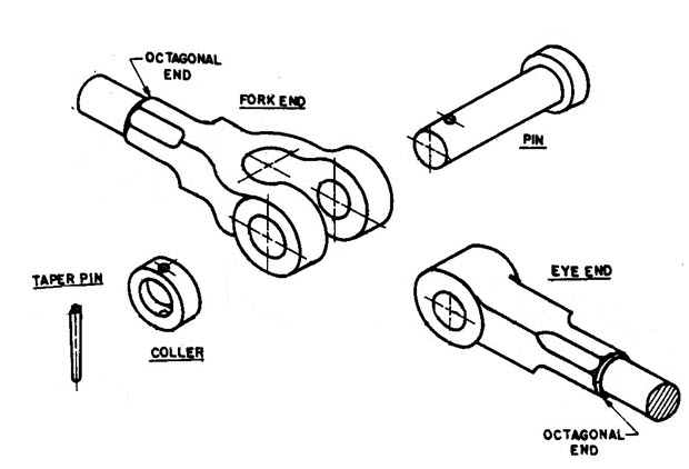
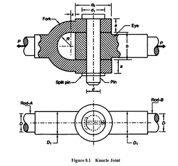
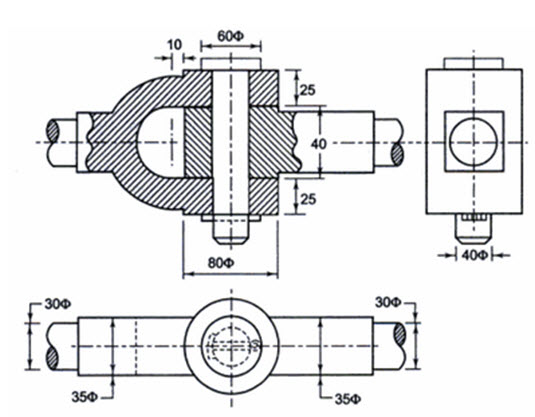
Knuckle Joint has mainly three components – eye, fork and pin as shown in Figure 8.1. Eye is formed on one of the rods and fork is formed on the other. Eye fits inside the fork and the pin is passed through both the fork and the eye. This pin is secured in its place by means of a split-pin. The ends of the rods are made octagonal to some distance for better grip and are made square for some portion before it is forged to make the eye and fork shapes.
Advantages of Knuckle Joint are:
- Simple to design and manufacture.
- Fewer parts – less cost more reliability.
- Simple to assemble and dismantle.
8.2 Design of Knuckle Joint
Notations Used
D = diameter of each rod (mm)
D1 = enlarged diameter of each rod (mm)
d = diameter of knuckle pin (mm)
d0 = outside diameter of eye or fork (mm)
d1 = diameter of pin head (mm)
a = thickness of each eye of fork (mm)
b = thickness of eye end of rod B (mm)
x = distance of the centre of fork radius R from the eye (mm)
Assumption for stress analysis of Knuckle Joint
- The rods are subjected to axial tensile force.
- The effect of stress concentration due to holes is neglected
- The force is uniformly distributed in different parts.
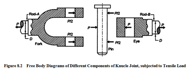
Figure 8.2 shows the free body diagrams of the three main components of knuckle joint subjected to a tensile force P.
In order to find out various dimensions of the parts of a knuckle joint, failures in different parts and at different x-sections are considered. The stresses developed in the components should be less than the corresponding permissible values of stress. So, for each type of failure, one strength equation is written and these strength equations are then used to find various dimensions of the knuckle joint. Some empirical relations are also used to find the dimensions.
8.2.1 Possible Failure Modes of Knuckle Joint
Tensile Failure of Rods :
Each rod is subjected to a tensile force P.
![]()
where [σ] = allowable tensile stress for the material selected.
Shear Failure of Pin :
The pin is subjected to double shear as shown in Figure 8.2
Total Area that resiststhe shear failure = \[2\left( {\frac{\pi }{4}{d^2}} \right)\]
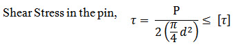
where [\[\tau\]] = allowable shear stress for the material selected.
Crushing Failure of Pin in Eye :
Projected Area of Pin in the eye = b d
![]()
where [σc] = allowable compressive stress for the material selected.
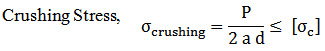
Crushing Failure of Pin in Fork :
Projected Area of Pin in the fork = 2 a d
Bending Failure of Pin :
When the pin is tight in the eye and fork, failure occurs due to shear, but when it is loose, it is subjected to bending moment as shown in Figure 8.5. It is assumed that: Load acting on the pin is uniformly distributed in the eye and uniformly varying in the two parts of the fork.
Maximum Bending Moment (at centre) =
\[M = \frac{P}{2}\left( {\frac{b}{2} + \frac{a}{3}} \right) - \frac{P}{2}\left( {\frac{b}{4}} \right)\]
Therefore, \[M = \frac{P}{2}\left( {\frac{b}{4} + \frac{a}{3}} \right)\]
Maximum Bending Stress in the pin,
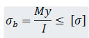
where,
\[I = \frac{{\pi {d^4}}}{{64}}andy = \frac{d}{2}\]
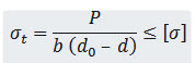
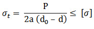
Tensile Failure of Eye :
Area of the weakest section of eye resisting tensile failure = b (d0 – d)
Maximum Tensile Stress in eye,
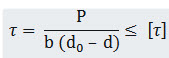
Shear Failure of Eye :
The eye is subjected to double shear
Total area resisting shear =
\[2{\text{}}\left[ {\frac{{{\text{b}}\left( {{{\text{d}}_0}{\text{}}-{\text{d}}} \right)}}{2}} \right] = {\text{b}}\left( {{{\text{d}}_0}{\text{}}-{\text{d}}} \right)\]
Maximum Shear Stress in eye =
Tensile Failure of Fork :
Area of the weakest section of fork resisting tensile failure = 2a (d0 – d)
Maximum Tensile Stress in fork =
Shear Failure of Fork :
Each of the two parts of the fork is subjected to double shear.
Total area resisting shear = \[2{\text{}}\left[ {\frac{{2{\text{a}}\left( {{{\text{d}}_0}{\text{}}-{\text{d}}} \right)}}{2}} \right]\] \[= {\text{}}2{\text{a}}\left( {{{\text{d}}_0}{\text{}}-{\text{d}}} \right)\]
Maximum Shear Stress in fork = 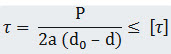
8.2.2 Design Procedure for Knuckle Joint
Some standard proportions for dimensions of the knuckle joint are taken as:
D1 = 1.1 D, d = D, d0 = 2d, a= 0.75 D, b = 1.25 D , d1 = 1.5 d & x = 10 mm
Dimensions can be determined using these empirical relations and the strength equations can be then used as a check. By doing so the standard proportions of the joint can be maintained. The other method, of designing it, can be making the use of above strength equations to find the dimensions mathematically.
Procedure to determine various dimensions of knuckle joint is as follows:
i) Calculate the Diameter of each rod using \[\frac{{\text{P}}}{{\frac{\pi }{4}{D^2}}} = \left[ \sigma\right]\]
ii) Calculate D1 for each rod using empirical relation \[{D_1} = 1.1D\]
iii) Calculate dimensions a and b also using empirical relations a = 0.75 D & b = 1.25 D
iv) Calculate diameter of the pin by shear and bending consideration and select the diameter which is maximum. \[\frac{P}{{2\left\{ {\frac{\pi }{4}{d^2}} \right\}}} = \left[ \tau\right]\] and \[\frac{{My}}{{I}} = \left[ \sigma\right]\]
v) Calculate dimensions d0 and d1 using empirical relations d0 = 2d and d1 = 1.5d
vi) Check the tensile, crushing and shear stresses in the eye
![]()
vii) Check the tensile, crushing and shear stresses in the fork
![]()
Last modified: Wednesday, 19 March 2014, 10:25 AM