Site pages
Current course
Participants
General
MODULE 1.
MODULE 2.
MODULE 3.
MODULE 4.
MODULE 5.
MODULE 6.
MODULE 7.
MODULE 8.
MODULE 9.
MODULE 10.
LESSON 11 DESIGN OF WELDED JOINTS
11.1 Design of a Butt Joint
The butt joints are designed for tension or compression. Average Tensile Stress in a butt welded joint subjected to tensile load, P is given by, ![]()
where, A is throat area, t is throat thickness and l is length of the weld.
σt must be ≤ [σt ] for the joint to be safe.
Similarly Average Compressive Stress in a butt welded joint subjected to compressive load, P is given by, ![]() , which must be ≤ [σc].
, which must be ≤ [σc].

i. Single V-Butt Joint ii. Double V-Butt Joint
Figure 11.1 Butt Joint
For double V-butt joint, throat area is (t1+t2) l, where t1 and t2 are throat thickness at top and bottom.
11.2 Design of a Fillet Joint
11.2.1 Transverse Fillet Weld
Transverse Fillet welds are designed for tensile strength. For strength calculations, the section of fillet is assumed to be a right angled triangle, with hypotenuse making equal angles with the two sides as shown in Figure 11.2.


Figure 11.2 Single & Double Transverse Fillet Weld
Length of each side (AB=BC) is known as size or leg of the weld (s) and the distance of the hypotenuse from the intersection of two legs (BD) is known as throat thickness (t). Minimum area is obtained at the throat. If l is the length of the weld,
Throat area, A = t l = s. sin 45°. l = 0.707 s l
Tensile Stress of single transverse fillet weld subjected to tensile load, P is given by,
![]()
And that for a double transverse fillet weld is given by,
![]()
11.2.2 Parallel Fillet Weld

Figure 11.3 Parallel Fillet Weld
Parallel fillet welds are designed for shear strength. Consider a parallel fillet weld as shown in Figure 11.3. Throat Area, A = 0.707 s l, where s and l are size and length of the weld.For a parallel fillet weld subjected to tensile load, P, shear stress is given by,
![]()
11.2.3 Combination of Transverse and Parallel Fillet Welds

Figure 11.4 Combination of Transverse & Parallel Fillet Weld
If a tensile load, P is applied on a combination of transverse and parallel fillet weld, shear stress will develop in the parallel fillet welds and tensile stress will develop in the transverse fillet weld such that the maximum load that the weld can withstand is given by,
P max = 1.414 s l1 [σt] + 1.414 s l2 [t]
= 1.414 s (l1 [σt] + l2 [t])
l1 and l2 are weld lengths on two sides, as shown in Figure 11.4.While designing any fillet weld, 11.5 mm length must be left on each side of the weld to allow for the start and stop of the bead.
11.3 Unsymmetrical Welded Sections
For unsymmetrical welded sections subjected to tensile loads as shown in Figure 11.5, the length of welds should be so proportioned that the resisting moment of the welds about the gravity axis is zero.

Figure 11.5 Axially Loaded Unsymmetrical Welded Sections
Let
la, lb = Length of welds on two sides
a , b = Distance of welds from gravity axis
l = Total length of weld = la + lb
P = Axial load,
f = Resistance offered by the weld per unit length.
Moment of resistance offered by weld on side A about gravity axis = la × f × a
Moment of resistance offered by weld on side B about gravity axis = lb × f × b
For the moments about the gravity axis to be zero,
la × f × a = lb × f × b => la × a = lb × b
Also, l = la + lb
Therefore, ![]() and
and ![]()
11.4 Eccentrically Loaded Welded Joints

Figure 11.6 Bending Stress due to Eccentricity
In many cases the welded joints are eccentrically loaded. Different stresses may get induced depending upon the type of joint and loading. if the stresses are of same nature , those may be vectorially added but for those of different nature, resultant maximum tensile and shear stresses may be calculated. Depending upon the type of joint, eccentricity may lead to bending stress or torsional shear stress in the joint in addition to the direct shear stress induced by applied load.
11.4.1 Eccentricity leading to Bending Stress
Consider a T-joint subjected to loading as shown in figure. Let s and l be the size and length of the weld and t be the throat thickness.
Throat area = A = 2 t l
This applied load may be considered as a load P directly acting on the joint through the CG and a bending moment of magnitude P.e acting on the joint. 1st one will lead to direct shear stress and the 2nd will lead to a bending stress.
Direct Shear Stress, ![]() and
and ![]() Bending Stress,
Bending Stress,
where y = distance of the point on the weld from the neutral axis
I = Moment of inertia of the weld section
Maximum tensile and shear stress may be calculated as:
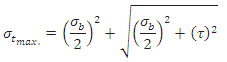 and
and 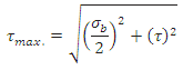
1.4.2 Eccentricity Leading to Torsional Shear Stress

Figure 11.7 Shear Stress due to Eccentricity
Let us consider a double parallel fillet weld subjected to an eccentric load P acting at a distance e from the CG of the welds as shown in Figure 11.7.
Eccentric force P may be considered as a force P acting on the CG of the joint and a torque equivalent to Pe acting on the joint. The force P through the CG leads to direct shear stress, called primary shear stress and is assumed to be uniformly distributed over the throat area of all welds. The torque Pe causes torsional shear stress called secondary shear stress.
Primary Shear Stress, ![]() and Secondary Shear Stress,
and Secondary Shear Stress, ![]()
where r = distance of the point on the weld from the CG
J = Polar moment of inertia of the weld section
r is calculated from the geometry for the farthest point of the weld from the CG.
Last modified: Thursday, 20 March 2014, 5:27 AM