Site pages
Current course
Participants
General
MODULE 1.
MODULE 2.
MODULE 3.
MODULE 4.
MODULE 5.
MODULE 6.
MODULE 7.
MODULE 8.
MODULE 9.
MODULE 10.
LESSON 9. DESIGN OF COTTER JOINT
9.1 Introduction
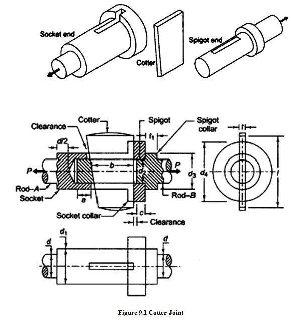
Cotter joint is used to connect two rods subjected to axial tensile or compressive loads. It is not suitable to connect rotating shafts which transmit torque. Axes of the rods to be joined should be collinear. There is no relative angular movement between rods. Cotter joint is widely used to connect the piston rod and crosshead of a steam engine, as a joint between the piston rod and the tailor pump rod, foundation bolt etc.
Cotter Joint has mainly three components – spigot, socket and cotter as shown in Figure 9.1. Spigot is formed on one of the rods and socket is formed on the other. The socket and the spigot are provided with a narrow rectangular slot. The cotter is tightly fitted in this slot. Spigot fits inside the socket and the cotter is passed through both the socket and the spigot. A cotter is a wedge shaped piece made of a steel plate. It has uniform thickness and the width dimension is given a slight taper. Taper is usually 1 in 24 and provides mainly two benefits: i) cotter becomes tight in the slot due to wedge action. This ensures tightness of the joint in operating conditions and prevents loosening of the parts. ii) Due to its taper shape, it is easy to remove the cotter and dismantle the joint.
The construction of cotter joint, used to connect two rods subjected to tensile force P is shown in the figure. When the cotter is inserted into the slot, the central portion of cotter comes in contact with spigot and the spigot gets pushed into the socket till the collar of the spigot comes in contact with the collar of socket. As shown in the figure, finally the cotter is in contact with the spigot on one side having some clearance with the socket slot and is in contact with the socket on the other side having some clearance with the spigot slot. Clearance provided is generally 1.5 to 3 mm. Cotter gets locked because of the frictional force of the contacting surfaces.
Advantages of Cotter Joint:
- Simple to design and manufacture.
- Simple to assemble and dismantle.
- Very high tightening force due to wedge action, which prevents loosening of parts in service.
9.2 Design of Knuckle Joint
Notations Used :
d = diameter of each rod (mm)
d1 = outside diameter of socket (mm)
d2 = diameter of spigot or inside diameter of socket (mm)
d3 = diameter of spigot-collar (mm)
d4 = diameter of socket-collar (mm)
a = distance from end of slot to the end of spigot on rod-B (mm)
b = mean width of cotter (mm)
c = axial distance from slot to end of socket collar (mm)
t = thickness of cotter (mm)
t1 = thickness of spigot collar (mm)
l = length of cotter (mm)
Assumption for stress analysis of Cotter Joint :
- The rods are subjected to axial tensile force.
- The effect of stress concentration due to holes is neglected
- The force is uniformly distributed in different parts.
Free body diagram of forces acting on three components of the cotter joint (socket, cotter and spigot) are shown in Figure 9.2.
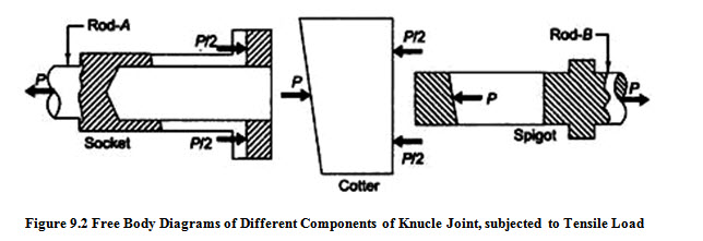
In order to find out various dimensions of the parts of a cotter joint, failures in different parts and at different x-sections are considered. The stresses developed in the components should be less than the corresponding permissible values of stress. So, for each type of failure, one strength equation is written and these strength equations are then used to find various dimensions of the cotter joint. Some empirical relations are also used to find the dimensions.
9.2.1 Possible Modes of Failure of Cotter Joint
Tensile Failure of Rods :
Each rod is subjected to a tensile force P.
Tensile stress in the rods = 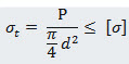
where [σ] = allowable tensile stress for the material selected.
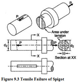
Tensile Failure of Spigot :
Area of the weakest section of spigot resisting tensile failure =
\[\left[ {\frac{\pi }{4}d_2^2 - {d_2}t} \right]\]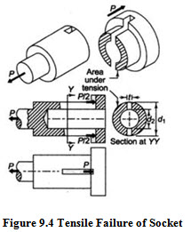
Tensile Stress in the Spigot = ![]()
Tensile Failure of Socket :
Area of the weakest section of socket resisting tensile failure =
\[\left[ {\frac{\pi }{4}(d_1^2 - d_2^2) - \left( {{d_1} - {d_2}} \right)t} \right]\]
Tensile Stress in the Socket = ![]()
Shear Failure of Spigot End :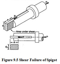
The spigot end is subjected to double shear.
Total area that resists the shear failure = 2ad2
Shear Stress in the socket = ![]()
where [\[\tau\]] = allowable shear stress for the material selected.
Shear Failure of Socket End :
The socket end is subjected to double shear.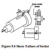
Total area that resists the shear failure = 2 \[\left( {{d_4} - {d_2}} \right)c\]
Shear Stress in the socket =![]()
Crushing Failure of Spigot End :
Area under crushing \[= {\text{t}}{{\text{d}}_2}\]
Crushing Stress = ![]()
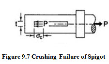
where [σc] = allowable compressive stress for the material selected.
Crushing Failure of Socket End :
Area under crushing \[= \left( {{d_4} - {d_2}} \right)t\]
Crushing Stress, 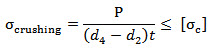
Shear Failure of Spigot Collar :
Area of spigot collar that resists the shear failure = \[\pi\] d2 t1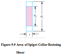
Shear Stress in the socket = 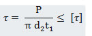
Crushing Failure of Spigot Collar :
Area of spigot collar under crushing = \[\frac{\pi }{4}(d_3^2 - d_2^2)\]
Crushing Stress = ![]()
Shear Failure of Cotter :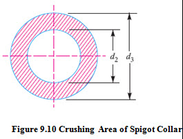
The cotter is subjected to double shear.
Total area of cotter that resists the shear failure = 2bt
Shear Stress in the pin = ![]()
Bending Failure of Cotter :
When the cotter is tight in the socket and spigot, failure occurs due to shear, but when it is loose, it is subjected to bending moment as shown in figur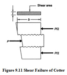 e.
e.
It is assumed that: the force between cotter and spigot end is uniformly distributed and uniformly varying between the socket end and cotter.
Maximum Bending Moment (at centre) =
\[M = \frac{P}{2}\left( {\frac{{{d_2}}}{2} + \frac{{{d_4} - {d_2}}}{6}} \right) - \frac{P}{2}\left( {\frac{{{d_2}}}{4}} \right)\]
\[= \frac{P}{2}\left( {\frac{{{d_2}}}{4} + \frac{{{d_4} - {d_2}}}{6}} \right)\]
Maximum Bending Stress in the cotter =
![]()
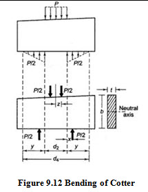
where,
\[I = \frac{{t{b^3}}}{{12}}andy = \frac{b}{2}\]
9.2.2 Design Procedure for Cotter Joint
Procedure to determine various dimensions of cotter joint is as follows:
i) Calculate the Diameter of each rod using \[\frac{{\text{P}}}{{\frac{\pi }{4}{d^2}}} = \left[ \sigma\right]\]
ii) Calculate thickness of cotter using empirical relation \[t = 0.31d\]
iii) Calculate diameter of the spigot on the basis of tensile stress \[\frac{{\text{P}}}{{\left[ {\frac{\pi }{4}d_2^2 - {d_2}t} \right]}} = \left[ \sigma\right]\]
iv) Calculate outside diameter of the socket on the basis of tensile stress
\[\frac{{\text{P}}}{{\left[ {\frac{\pi }{4}(d_1^2 - d_2^2) - \left( {{d_1} - {d_2}} \right)t} \right]}} = \left[ \sigma\right]\]
v) Diameter of spigot collar, d3 and diameter of socket collar, d4 are determined using empirical relations d3 = 1.5 d and d4 = 2.4 d
vi) Dimensions a and c are also determined using empirical relations a = c = 0.75 d.
vii) Calculate width of cotter by shear and bending consideration and select the width which is maximum, \[\frac{{\text{P}}}{{2bt}} = \left[ \tau\right]\]
and \[\frac{{My}}{{I}} = \left[ \sigma\right]\]
viii) Check the crushing and shear stresses in the spigot end.
![]()
ix) Check the crushing and shear stresses in the socket end
![]()
x) Calculate thickness t1 of spigot collar by the following empirical relationship \[{t_1} = 0.45d\]
xi) Check the crushing and shear stresses in the socket collar
![]()
Last modified: Wednesday, 19 March 2014, 12:01 PM