Site pages
Current course
Participants
General
Module 1. Perspective on Soil and Water Conservation
Module 2. Pre-requisites for Soil and Water Conse...
Module 3. Design of Permanent Gully Control Struct...
Module 4. Water Storage Structures
Module 5. Trenching and Diversion Structures
Module 6. Cost Estimation
Lesson 23. Earthen Embankment
23.1 Introduction
An earthen embankment is a raised confining structure made from compacted soil to confine runoff either for surface storage or for ground water recharge. These are also used for increasing infiltration; detention and retention of water to facilitate deep percolation and also to provide additional storage as in the case of semi dug-out ponds. The cross-section of embankments is usually trapezoidal in shape. When constructed across natural channel to induce channel storage, the embankment also called earthen dam. Further, the embankment depends on its own weight to resist against sliding and overturning whereas foundation work is also included in case of dam. However, at many instances both terms are used as synonymously.
The earthen embankment meant to collect surface runoff or overland flow can be compared with field bunds in many respect except the difference in height and catchment area. In the case of field bunds, the height are usually less than 50 cm and catchment area is limited up to 0.5 ha whereas in case of embankments the minimum height is 3 m and can be as high as 10m and catchment area can be tens of hectare.
Advantages and disadvantage of small earthen embankment/dam:
The major advantages include.
Local natural materials are used.
Design procedures are straightforward.
Comparatively small plant and equipment are required.
Foundation requirements are less stringent than for other types of dam. The broad base of an earth dam spreads the load on the foundation.
Earth fill dams resist settlement and movement better than more rigid structures and can be more suitable for areas where earth movements are common.
The disadvantages are
An earth embankment is easily damaged or destroyed by water flowing on, over or against it. Thus, a spillway and adequate upstream protection are essential for any earth dam.
Designing and constructing adequate spillways is usually the most technically difficult part of any dam building work. Any site with a poor quality spillway should not be used.
If it is not adequately compacted during construction, the dam will have weak structure hence prone to seepage.
Earth dams require continual maintenance to prevent erosion, tree growth, subsidence, animal and insect damage and seepage.
23.2 Types of Embankment
The type of embankment depends on the purpose of storm water to be used such as detention and retention, ground water recharge, surface water harvesting etc. and the available soil material for construction. Broadly, two type of embankment can be assumed, namely, homogenous embankment and zoned embankment.
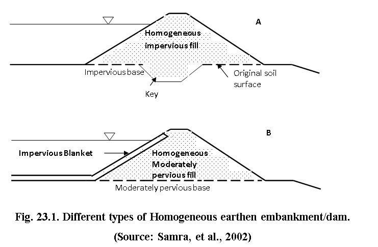
23.2.1 Homogeneous
It is composed of one kind of material (excluding slope protection). The material used must be sufficiently impervious to provide an adequate water barrier, and the side slopes must be moderately flat for stability and ease of maintenance (Fig. 23.1). The homogeneous soil material is either keyed in to the impervious base (see Fig. 23.1 A) or impervious soil material can be placed as blanket to the upstream slope of the embankment (see Fig. 23.1 B).
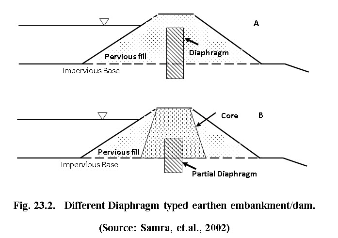
Diaphragm: The bulk of material used for construction of the embankment is pervious. A thin diaphragm of impermeable material like (concrete, steel, butyl etc.) is provided to act as barrier against seepage through the fill. The full diaphragm condition occurs when the upper crest of diaphragm and design water depth are at the same level (see Fig. 23.2 A). There are cases when the full diaphragm is difficult to adopt, partial diaphragm can be adopted in conjunction with core wall (Fig. 23.2 B).The core walls usually are made of the earth with low hydraulic conductivity.
23.2.2 Zoned Earth Dams
It contains a central impervious core, surrounded by zones of more pervious material, called shells. These pervious zones or shells support and protect the impervious core (Fig. 23.3).
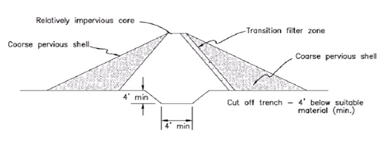
Fig. 23.3. Zoned Earth Dam. (Source: www.dcr.virginia.gov/stormwater)
23.3 Methods of Construction
Earthen dams are either constructed as rolled fill or hydraulic fill dams.
(a) Rolled Fill Dam: In this type of dams, successive layers of moistened or damp soils are laid one over one another. Each layer not exceeding 20 cm in thickness is properly consolidated at optimum moisture content which is maintained by sprinkling water and compacted by mechanical roller only then the next layer laid.
(b) Hydraulic Fill Dam: In this type of dams, the construction, excavation, transportation of the earth is done by hydraulic methods. Outer edges of the embankments are kept slightly higher than the middle portion of each layer. During construction, a mixture of excavated materials in slurry condition is pumped and discharged at the edges. This slurry of excavated materials and water consists of coarse and fine materials. When it is discharged near the outer edges, the coarser materials settle first at the edges, while the finer materials move to the middle and settle there. Fine particles are deposited in the central portion to form a water tight central core. In this method, compaction is not required.
23.4 Site selection and Investigation for Earthen Embankment/Dam
The embankment should be proposed based on site specific considerations to prevent hydraulic, seepage and structural failure of dam. The common causes of dam failure are illustrated in Fig. 23.4. These are discussed in detail in lecture 24.

(Source: Kunitomo, 2000)
23.5 Design of Earthen Embankment
The various components of earthen embankment includes (a) base/foundation including key trench or cut-off, (b) height, (c) side slopes, (d) top width, (e) free board, (f) toe drains or filter and (g) core wall.
23.5.1 Design Steps
Preliminary Investigations
Although the selection of a suitable site is essentially a field exercise, the use of aerial photographs and large-scale maps can provide a useful assessment of the local topography and hydrological conditions before any field visit takes place. Once possible sites are identified, a field visit is essential. It is important to identify where the water to be stored is to be used: irrigation, for example, involves the conveyance of large quantities of water and, if the dam-site is a long distance away from the cultivated area, much expenditure on pipelines and pumping may be required.
The economic and design implications of each site can be determined from a brief preliminary survey. The survey must be sufficiently accurate and detailed to enable comparative estimates to be made for various heights of dam. The most economic height is usually calculated on the basis of cost per unit volume of water.
Catchment Yield
The catchment yield, ‘Y’, is based on the expected annual runoff from a catchment and is an important factor in assessing the feasibility of a dam and in determining the required height of the embankment. The latter is important to allow the dam designer to size the dam to suit expected inflow. It is estimated as follows:
Calculate the annual runoff for the catchment, in mm. This is ‘RF’.
Measure the catchment area ‘A’ in km2, upstream of the proposed embankment.
The annual runoff for the catchment (the catchment yield in an average year), Y, in m3, is given by:
Y = RF x A x 1 000 (23.1)
Storage Capacity
At this stage, this is worked out as follows:
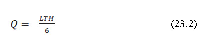
Where, Q is the storage capacity in m3 and should not exceed Y above, L is the length of the dam wall at full supply level (FSL) in m, T is the throwback, in m and approximately in a straight line from the wall. H is the maximum height of the embankments, in m, at FSL. 6 is a factor (conservative generally) that can be adjusted (to 5 or 4) with experience and local knowledge.
Equation 23.2 considers the water volume to be an inverted pyramid with a triangular surface area (LT/2) and H/3 for the height/depth, and is a simplification of reality.
Further, general guidelines for homogeneous embankment are given in Table 1 and design steps are given below:
Height of the Embankment
The height of the embankment is determined using depth-capacity curve and reservoir area capacity curve. The other consideration is to obtain the minimum cost of embankment per unit storage. The overall height however, should not exceed 10 m.
Free Board
The free board is the added height to the embankment as a safety measure to prevent the ill effect of waves and runoff generated from storms greater than the designed frequency. The free board is the difference between highest flood level and top level of the embankment after complete settlement taken place. Generally, 10-15% free board is provided to the highest flood level. The free board also depend on length of the embankment. Additional 50 cm free board is provided for the embankment length upto 400m. For 400-800 m length and greater than 800 m length, the additional freeboard of 75 cm and 100 cm is provided respectively.
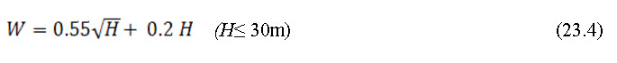
Top width can be calculated using formula
![]()
Wave height can be calculated using Hawksley’s formula
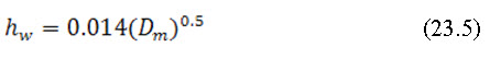
Where, hw is wave height (m),Dm is longest fetch distance (m).
Settlement Allowance
Settlement includes the consolidation of the fill material and base material due to self-weight and increased moisture of the embankment body due to storage of water. The settlement allowance varies from 5% (machine compacted) to 10% (manual compacted). The settlement allowance is added to the height of the embankment over and above the calculated free board.
Table 23.1. General guidelines for embankment section (Homogeneous section)
|
Sl. No |
Description |
Height upto 5m |
Height between 5 and 10 m |
||
|
1. |
Slopes |
U/S |
D/S |
U/S |
D/S |
|
2 |
Soil |
|
|
|
|
|
|
Well graded gravel and sand |
Not suitable |
Not suitable |
Not suitable |
Not suitable |
|
|
Gravel and sand with silt and clay |
2:1 |
2:1 |
2:1 |
2:1 |
|
|
Silt and clay with low compressibility |
2:1 |
2:1 |
2.5:1 |
2.5:1 |
|
|
Silt and clay with high compressibility |
2:1 |
2:1 |
3.75:1 |
2.5:1 |
|
3 |
Rock toe height |
Not necessary up to 3 m. above 3 m, 1 m rock toe should be provided |
Necessary, height should be H/5 where H is the height of embankment |
||
|
4 |
Top width |
Minimum 2 m |
Minimum 2.5 m |
||
|
5 |
Free board |
Min 2 m and max 3 m over maximum flood level |
|||
Design Example 23.1:
Design an earthen embankment with the following data
RL of bed surface =116.0 m. RL of Highest Flood Level (HFL) = 122.5 m.
Assume a fetch of 1.5 km and slope of saturation line is 4:1. Length of the embankment is 350 m.
Solution:
Height of water upto HFL =122.5 - 116.0 = 6.5 m.
Calculation of free board
Wave height for a fetch of 1.5 km,
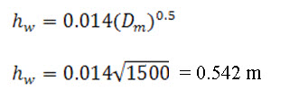
= 0.542 m
Free board (15%) = 6.5*.15 = 0.98 m
Since, free board is more than height of waves, 0.98 m value is adopted.
Free board adjustment for length of embankment
The length of embankment of 350 m less than 400 m and hence 40 cm to be added to the existing freeboard.
Thus total free board = 0.98+0.40 = 1.38 m
Hence, height of dam = 6.5 + 1.38 = 7.88 m
Assuming 5% settlement allowance, = 7.88*0.05 = 0.394= say 0.40m
Thus overall height of proposed dam =7.88 + 0.40 = 8.28 m say 8.25 m
Top width of the dam =![]() = 3.15 m (say 3.5 m).
= 3.15 m (say 3.5 m).
Determining base width of the embankment and its stability
Assuming upstream and downstream slopes of 3:1 and 2.5:1, respectively, the base width is
Wb = 3*overall height of embankment+top width+2.5*overall height of embankment
Wb = 3*8.25+3.5+2.5*8.25 = 48.38m
Normal projection of saturation line over the base = 3*6.5+4*6.5 = 45.5 m.
Since the design base width is greater than the normal projection of the saturation line. Therefore, the d/s face of the embankment will be dry and saturation line will converges within the base width. Hence the design is safe and stable. Typical cross-section of the embankment is shown in Fig..23.5
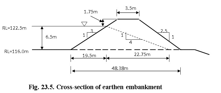
In case, the seepage line or saturation line does not meet the base of the embankment, then modifications in the different components of the embankment is needed for embankment safety and stability. One such modification can be the case when highest flood level is at 125.25 m instead of present 122.5 m.
References
-
Suresh, R. (1993). Soil and Water Conservation Engineering. New Delhi, Standard Publishers and Distributors.
-
FAO. (2010). Manual on small earth dams. Food and Agricultural Organization of United Nations, Roam.
-
http://www.fao.org/docrep/012/i1531e/i1531e.pdf (last accessed 3.9.12)
-
Samra, J.S., Sharda, V.N. and Sikka, A.K. (2002). Water Harvesting and Recycling – Indian Experience, CSWCRTI, Dehradun.
Internet References
-
Kunitomo, N. (2000). Design and construction of embankment dams. (http://aitech.ac.jp/~narita/tembankmentdam1.pdf, accessed on 17 Oct., 2013).
-
http://www.fao.org/docrep/012/i1531e/i1531e00.pdf, accessed on 17 October 2013.
-
http://www.fao.org/docrep/012/i1531e/i1531e01.pdf, accessed on 17 October 2013.
Suggested Reading
-
Suresh, R. (1993). Soil and Water Conservation Engineering. New Delhi, Standard Publishers and Distributors.
-
FAO. (2010). Manual on small earth dams. Food and Agricultural Organization of United Nations, Roam.
-
http://www.fao.org/docrep/012/i1531e/i1531e.pdf (last accessed 3.9.12)
-
Samra, J.S., Sharda, V.N. and Sikka, A.K. (2002). Water Harvesting and Recycling – Indian Experience, CSWCRTI, Dehradun.
Last modified: Thursday, 13 February 2014, 11:20 AM