Site pages
Current course
Participants
General
Module 1. Perspective on Soil and Water Conservation
Module 2. Pre-requisites for Soil and Water Conse...
Module 3. Design of Permanent Gully Control Struct...
Module 4. Water Storage Structures
Module 5. Trenching and Diversion Structures
Module 6. Cost Estimation
Lesson. 25 Seepage Analysis
Seepage is the horizontal flow of water through the soil pore space. The seepage generally implied to the dominant horizontal flow in porous media. Seepage is the more commonly phenomenon in soil and water conservation structures and hence it assumes great significance in addressing the issue of stability of hydraulic structures mostly earthen type.
25.1 One Dimensional Flow
The flow through the saturated soil mass takes place from point of higher energy to point of lower energy as represented by head. The total head at any point in the soil mass consists of piezometric head, velocity head and elevation head. This can be represented by Bernoulli equation as below:
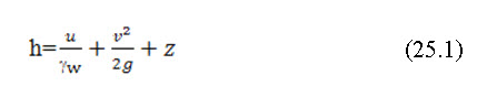
Where the first term is pressure head, second term is velocity head and the third term is elevation head and also h is the total head, u is the pressure, v is the velocity, g is the acceleration due to gravity and gw is the unit weight of water.
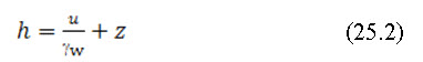
In soils the velocity of flow is very small and thus velocity head can be neglected in comparison to other heads. Eq. (25.1) becomes:
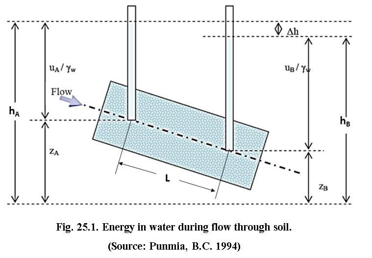
The relationship among pressure, elevation and total heads for the flow through soils is shown in Fig. 25.1. The pressure head at a point is the height of the vertical column of water in the peizometer installed at that point. The elevation head of a point is the vertical distance measured from any arbitrary horizontal reference datum plane to the point. Therefore, total head at points A and B, separated by distance L, is hA and hB, respectively.
The loss of head between point andcan be given by
The head loss Δh, can be expressed in a non-dimensional form as
Where,I is the hydraulic gradient; and Lis the distance between points A and B, that is the length of flow over which the loss of head occurred.
25. 2 Darcy’s Law
Darcy's law states that under the laminar flow conditions velocity of flow is directly proportional to hydraulic gradient and it can be expressed as:
Where, vis the discharge velocity, which is the quantity of water flowing in unit time through a unit gross cross sectional area of soil at right angles to the direction of flow and k is the hydraulic conductivity.
The Darcy's equation v is discharge velocity and is based on gross cross sectional area. However the actual velocity of water (known as seepage velocity and represented by vs) through the void spaces is higher than v.
25.3 Two Dimensional Flow
In many practical situations, such as flow around a sheet pile wall, under masonry dams and through earth dams, flow is two dimensional, i.e., the velocity components in the horizontal and vertical directions vary from point within the cross section of soil mass. The two dimensional flow of water through soil is governed by Laplace’s Equation. The assumption and its implications (in bracket) associated with Laplace’s equation are presented below.
-
Darcy's law is valid (Flow is laminar)
-
The soil is completely saturated (Degree of saturation is 100%)
-
The soil is homogeneous (Coefficient of permeability is constant)
-
The soil is isotropic (Coefficient of permeability is same in all directions)
-
During flow, the volume of soil & water remains constant (No expansion or contraction)
-
The soil and water are incompressible (No volume change occurs).
For isotropic conditions, Laplace’s Equation representing the two dimensional flow of water through soil can be expressed as:
This is the Laplace equation for isotropic soil. It says, the change of gradient in x-direction plus change in gradient in y-direction is zero. Graphical solution of Lapalce equation results flow net.
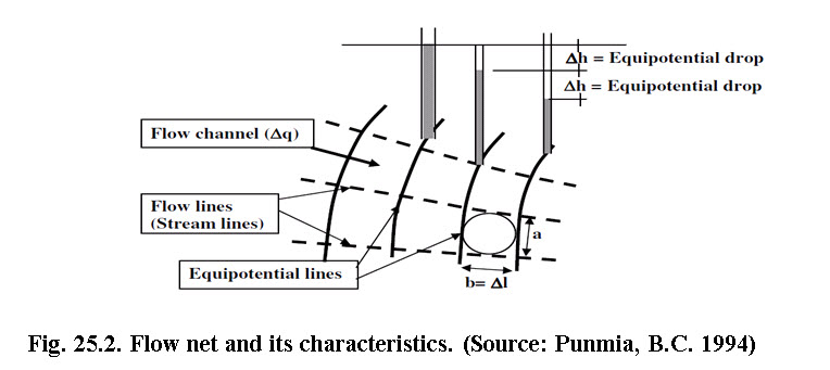
25.3.1 Flow Net
When Laplace equation is solved graphically the equation gives flow net consisting two sets of curves intersecting at right angles known as flow lines (or stream lines) and equipotential lines.
25.3.2 Characteristics of Flow Net
-
Flow lines or stream lines represent flow paths of particles of water
-
Flow lines and equipotential line are orthogonal to each other
-
The area between two flow lines is called a flow channel
-
The rate of flow in a flow channel is constant (∆q)
-
Flow cannot occur across flow lines
-
An equipotential line is a line joining points with the same head
-
The velocity of flow is normal to the equipotential line
-
The difference in head between two equipotential lines is called the potential drop or head loss (∆h).
-
A flow line cannot intersect another flow line.
-
An equipotential line cannot intersect another equipotential line.
25.3.2 Quantity of Seepage
Let b and l are the width and length of the field respectively; h is the head drop between two equipotential lines; Q is the discharge passing through the flow channel of flow net; Δh is the total head, causing the flow.
The seepage rate (q) through the dam can be computed from the flownet. According to the Darcy’s law, the seepage water through a single flow channel is equal to:
![]()
Consider unit thickness of field 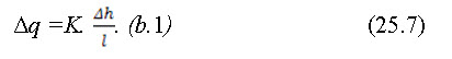
If the field thickness is taken as unit and total number of potential drops in the entire flow net is Nd, then Δh = h/Nd; and Eq. 25.7 is written as,

Hence total discharge passing through the entire flow net is given by
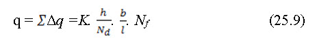
in which Nf is the total number of flow channels in the flow net. Since the field is in square in shape, hence b = l. Thus, Eq. (25.9) is reduced to:
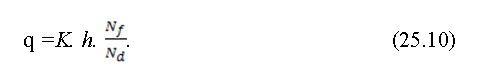
This expression can be used for computing the discharge rate passing through the flow net. It is applicable only to the isotropic soils.
Example 25.1:
For a homogeneous earth dam 52 m high and 2 m free board, a flow net was constructed and following results were obtained:
Number of potential drops = 25
Number of flow channels = 4
The dam has a horizontal filter of 40 m length at its downstream end. Calculate the discharge per metre length of the dam if the coefficient of permeability of the dam material is 3 10-3 cm/sec

References
-
Das, B. M. (2007). Advanced Soil Mechanics, Third edition, CRC, Press.
-
Das, G. (2008).Hydrology and Soil Conservation Engineering. PHI Learning PVT. LTD. New Delhi.
-
Lambe, T.W. and Whitman, R.V. (1979). Soil Mechanics. SI Version, John Wiley & Sons, New York
-
Murthy, V. N. S. (2002). Geotechnical Engineering. Principles and Practices of Soil Mechanics and Foundation Engineering", Marcel Dekker, Inc.,
-
Punmia, B.C. (1994). Soil Mechanics and Foundations, Thirteenth Edition, Laxmi Publications (P) Ltd., New Delhi.
-
Suresh, R. (1993). Soil and Water Conservation Engineering. Standard
-
Publishers and Distributors, New Delhi.
Suggested Reading
-
Das, B. M. (2007). Advanced Soil Mechanics, Third edition, CRC Press
-
Murthy V. N. S. (2002). Geotechnical Engineering. Principles and Practices of Soil Mechanics and Foundation Engineering", Marcel Dekker, Inc.
-
Punmia, B.C. (1994). Soil Mechanics and Foundations, Thirteenth Edition, Laxmi Publications (P) Ltd., New Delhi.
-
Suresh, R. (1993). Soil and Water Conservation Engineering. Standard Publishers and Distributors, New Delhi
Last modified: Wednesday, 12 March 2014, 5:35 AM