Site pages
Current course
Participants
General
Module 1: Fundamentals of Reservoir and Farm Ponds
Module 2: Basic Design Aspect of Reservoir and Far...
Module 3: Seepage and Stability Analysis of Reserv...
Module 4: Construction of Reservoir and Farm Ponds
Module 5: Economic Analysis of Farm Pond and Reser...
Module 6: Miscellaneous Aspects on Reservoir and F...
Lesson 7 Components of Embankment
The functions and design requirements of the components of embankment dams are discussed below:
7.1 Cutoff Trenches
Most of the embankment dams can benefit from the construction of a cutoff in the foundation. A cutoff serves the following purposes:
a) It reduces the seepage loss of stored water through foundations and abutments
b) It prevents subsurface erosion by piping
c) It improves the stability of the dam
These trenches are classified into two general types such as sloping-side trenches and vertical-side trenches. The cutoff trench should be located upstream from the centerline of the crest of dam, but not beyond a point where the cover of impervious embankment above the trench will fail to provide resistance to percolation at least equal to that offered by the trench itself. The centerline of this trench should be kept parallel to the centerline to the dam across the canyon bottom or valley floor. However, it should converge towards the centerline of the dam as it is carried up the abutments in order to maintain the required embankment cover. Whenever economically feasible, the seepage through a pervious foundation should be cut off by a trench extending to bedrock or other impervious stratum. This is the most positive means of controlling the amount of seepage and ensures no difficulty while piping through the foundation or by uplift pressure at the downstream toe.
The type of cut-off should be decided on the basis of detailed geological investigations. It is desirable to provide a positive cut-off. Where this is not possible, partial cutoff with or without upstream impervious blanket may be provided. In some cases, adequate drainage arrangements may be provided on the downstream which may, inter-alia, includes relief well. Cut-off may be in the form of trench, sheet piling, cement-bound curation, diaphragm of bentonite clay, concrete or other impervious materials.
7.2 Core
The core provides impermeable barrier within the body of the dam. Impervious soils are generally suitable for the core. IS: 1498-1970+ may be referred to for suitability of soils for the core. However, highly compressible soils with high liquid limit and organic content may be avoided for the core as they are prone to swelling and formation of cracks.
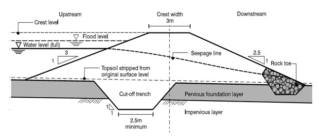
Fig. 7.1. Section through earthen embankment.
(Source: http://www.enggpedia.com/images/Cross-section-earth-dam.PNG)
The core may be located either centrally or inclined to the upstream face. The location of the core depends mainly on the availability of materials, topography of site, foundation conditions, diversion considerations, etc. The main advantage of a central core is that it provides higher pressure at the contact between the core and the foundation reducing the possibility of leakage piping. On the other hand, inclined core reduces the pore pressure in the downstream part of the dam and thereby increases its safety. It also permits the construction of downstream casing ahead of the core. The section with an inclined core allows the use of relatively large volume of random material on the downstream side.
The following practical considerations govern the thickness of the core:
Availability of suitable impervious material
Resistance to piping
Permissible seepage through dam
Availability of other materials for casing, filter, etc.
Minimum top width that will permit proper construction
7.3 Casing
The function of the casing is to impart stability and protect the core. Relatively pervious materials, which are not subject to cracking on direct exposure to the atmosphere, are suitable for casing.
7.4 Internal Drainage System
Internal drainage system comprises an inclined vertical filter, a horizontal filter, a rock toe and a toe drain etc. As far as possible, locally available sands and gravels should be used for this purpose.
The design of filter consists of applying the conventional filter criteria which take into account only the grain size distribution and the shape of grains. However, in addition to the grain size, the stability of base soil adjacent to a given filter depends on its resistance to drag forces. In view of this, when the soil containing 20% or more clay is used as base soil and has non-dispersive properties, the filter criteria may not be enforced strictly and the clean sand available locally may be used irrespective of the gradation. This relaxation should be applied to dams up to 10 m height only. For dams of height more than 10 m, the criteria for filters protecting cohesive soil may be relaxed by the designer depending upon his judgment and experience.
Inclined or vertical filter together with the base filter, if required, is desirable to be provided especially to protect silty core material. However, the inclined or vertical filter may be deleted in zoned sections having pervious downstream shell and clayey cores. Moreover, transition filter between the core and the downstream shell would be necessary in case of dam where rock fill is used as shell material. In case of dam reaches, where the head of water is 3 m or less, it may not be necessary to provide blanket or chimney filters. In this case, adequate toe protection shall, however, be provided.
Wherever silt material is to be filled in the cut-off and the downstream face of the cut-off is sufficiently open to receive soil particles migrating under high seepage gradients, it is advisable to provide a protective filter layer along the downstream face of the cut-off trench also.
Grouting of foundation is a process of injecting a fluid sealing material under pressure into the underlying formations through specially drilled holes for the purpose of sealing off or filling joint seams, fissures, or other openings. Unless the geologic conditions dictate otherwise, the foundation should be grouted to a depth below the surface of the rock equal to the reservoir head which lies above the surface of the rock.
The grouting of a dam foundation is usually performed along a single line of grout holes, with center to center distance of 10 to 20 feet. It creates a deep, impermeable water barrier referred to as "ground curtain". Multiple lines of grout holes may be used when severely fractured or highly permeable rock is encountered.
Keywords: Cutoff, Core, Casing, Filter, Piping, Grouting
Suggested Readings
USDI (1974). Design of small dams. Bureau of reclamation. United states Department of the Interior. Oxford and IBH publishing.
ISB (1987). Indian standard criteria for design of small embankment dams (IS:12169 -1967).
Last modified: Monday, 3 February 2014, 6:17 AM