Site pages
Current course
Participants
General
Module 1: Fundamentals of Reservoir and Farm Ponds
Module 2: Basic Design Aspect of Reservoir and Far...
Module 3: Seepage and Stability Analysis of Reserv...
Module 4: Construction of Reservoir and Farm Ponds
Module 5: Economic Analysis of Farm Pond and Reser...
Module 6: Miscellaneous Aspects on Reservoir and F...
Lesson 8 Basic Design Concept I
8.1 Site Selection
Selection of site is a very essential exercise in construction of reservoir or dam. The Selection of a site for constructing a dam should be governed by the following factors:
1. Suitable foundations must be available at the proposed site of the dam.
2. For economy, the length of the dam should be as small as possible, and for a given height, it should store the maximum volume of water. It, therefore, follows that the river valley at the dam site should be narrow but should open out upstream to provide a large basin for a reservoir. A general configuration of contours for a suitable site is shown in Fig.8.1.
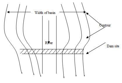
Fig. 8.1. Configuration of contours for a suitable dam site.
(Source: Garg, 2012)
3. The general bed level at dam site should preferably be higher than that of the river basin. This will reduce the height of the dam and will minimize the drainage problem.
4. A suitable site for the spillway should be available in the near vicinity of the dam. If the spillway is to be combined with the dam, the width of the gorge should be such as to accommodate both. The best dam site is one, in which a narrow deep gorge is separated from the flank by a hillock with its surface above the dam, as shown Fig 8.2. If such a site is available, the spillway can be located separately in the flank, and the main valley spanned by an earthen or similar dam. Sometimes the spillway and concrete masonry dam may be compositely spanned in the main gorge, while the flanks are by earth at low cost.
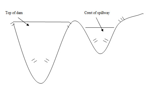
Fig. 8.2. Criterion for dam site. (Source: Garg, 2012)
5. Materials required for the construction of dam should be easily available in the locality so that the cost of transportation remains as low as possible.
6. The reservoir basin should be reasonably water tight. The stored water should not escape out through its side walls and bed.
7. The value of land and property likely to be submerged by the proposed dam should be as low as possible.
8. The dam site should have an easy access to important towns and cities by rails, roads, etc.
9. Site for establishing labour colonies with a healthy environment should be available at the proximity of the dam site.
8.2 General Design Considerations for Earth Dam
A fill of sufficiently low permeability should be developed out of the available materials, so as to best serve the intended purpose with minimum cost. Borrow pits should be as close to the dam site as possible, so as to reduce the leads.
Spillway and outlet capacities should be sufficient enough to avoid the possibility of overtopping during design flood.
Sufficient freeboard must be provided for wind set-up, wave action, frost action and earthquake motions.
The seepage line should remain well within the downstream face of the dam, so that no sloughing off the face occurs.
There should not be any possibility of free flow of water from the upstream to the downstream face.
The upstream face should be properly protected against wave action. The downstream face should be protected against rains and wave action due to tail water. Provisions of horizontal berms at suitable intervals in the downstream face may be thought of, so as to reduce the erosion due to direct flow of rain water. Ripraps should be provided on the entire upstream face, downstream slope near the toe and slightly above the tail water so as to avoid erosion.
The portion of the dam, downstream of the impervious core, should be properly drained by providing suitable horizontal filter drain or toe drain or chimney drain.
The upstream and downstream slopes should be so designed as to provide stability under worst conditions of loading. These critical conditions occur for the upstream slope during sudden drawdown of the reservoir, and for the downstream slope during steady seepage under full reservoir condition.
The upstream and downstream slope should be flat enough to provide sufficient base width at the foundation level. It keeps the developed shear stress below the maximum shear strength of the soil and provides a suitable factor of safety.
Consolidation of the soil does not take place instantaneously following compaction by external loadings. It takes place slowly as the excess pore water goes out and the load is transferred to the soil grains. However, in coarse gravels, the void openings are large enough so as to permit rapid escape of confined water and air resulting in full compaction before the construction is over. But in fine grained impervious soils, the consolidation is very slow. Therefore, it becomes necessary, in such cases, to provide an additional height of the fill. After complete consolidation is attained, the embankment comes back to the desired height. Hence, a suitable allowance in the height of embankment must be made in case of fine grained soils to take into account the delay in consolidation, which sometimes takes place even after years of construction. Dewatering the foundations may sometimes be used to accelerate the process of consolidation.
The stability of the embankment and foundation is very critical during construction or even after construction (during the period of consolidation) due to development of excessive pore pressures and consequent reduction in shear strength of soil. Hence, the embankment slopes must remain stable and safe under this critical condition.
All the above criteria must be satisfied and accounted for, in order to obtain a safe design and construction of an earth dam.
8.3 Harvesting Principles and its Components
Like other hydraulic structures, the design principle of water harvesting structures requires a wide range of input. In many regions, local thumb rules are used for designing the structures. For hydrological design, a more or less universal criterion is followed which is basically the ratio of the catchment area to the cultivated area (Fig. 8.1). When the ratio is known or assumed, the possible size of the field to be irrigated by harvested water can be easily determined. The size of the catchment can be assessed either by conducting field survey or from the topographic map of the catchment subject to availability of the map.
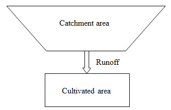
Fig. 8.1. Basic principle of water harvesting. (Suresh, 2002)
In most parts of the world, based on thumb rule the ratio ranges from 1:5 to 1:40 depending upon the rainfall magnitude and its distribution, watershed characteristics, runoff coefficient and water requirements of the crops to be irrigated. The thumb rule ratio i.e. the ratio of catchment area to cultivated area is defined as the ratio of the difference between crop water requirement and design rainfall to the product of design rainfall, runoff coefficient and efficiency factor.
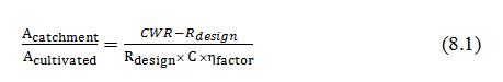
Where, Acatchment= Catchment area; Acultivated= Cultivated area; CWR = crop water requirement; Rdesign= design rainfall; C= runoff coefficient and ηfactor = efficiency factor.
Crop Water Requirement (CWR)
The term crop water requirement is defined as the amount of water required to compensate the evapotranspiration loss from the cropped field. Each type of crop has its own water requirements. For example, a fully developed maize crop will need more water per day than a fully developed crop of onion. Within the same type of crop however, there can be considerable variation in water requirements. The crop water requirement consists of transpiration and evapotranspiration usually referred to as evapotranspiration. It is computed based on the pan evaporation data and crop coefficients. The crop water requirement is a function of the specific crops to be grown and the prevailing climatic conditions. It is influenced by the climate in which the crop is grown. For example, a certain maize variety grown in a cool and cloudy climate will need less water per day than the same grown in a hot and sunny climate. Where evaporation data is not available, the estimation of crop water requirement can also be made based on experience or using the data from similar climatic areas.
Design Rainfall (Rdesign)
It is defined as the quantity of rainfall according to which a water harvesting system is designed. The difficulty with selecting the right design rainfall is the high variability of rainfall in arid or semi-arid regions. While the average annual rainfall might be 400 mm there may be years without any rain at all and wet years with 500 – 600 mm of rain or even more. If the actual rainfall is less than the design rainfall, the catchment area will not produce enough runoff to satisfy the crop water requirements; if the actual rainfall exceeds the design rainfall there will be too much runoff which may cause damage to the water harvesting structure. It is also expressed as the rainfall amount which may be expected during a rainy season with a probability of occurrence of 33%. The water supply is said to be inadequate if the rainfall in a given season does not exceed the design rainfall. On the other hand, when rainfall in a rainy season exceeds the design rainfall, it is called surplus water and required to be drained out from the crop area or harvested for reuse in during dry spells.
Runoff Coefficient
It denotes the percent of rainfall which flows down the slope as surface runoff. The proportion of total rainfall which becomes runoff is called the runoff coefficient. A runoff coefficient of 0.20 means 20% of all rainfall during the growing season becomes runoff. Every individual rainstorm has its own runoff coefficient. However, the seasonal or annual runoff coefficient is important for the design of a water harvesting system. It is a function of degree of land slope, soil type and geology, vegetative cover, antecedent rain and rainfall intensity. he coefficient can also be derived from the rainfall and stream flow data.
Efficiency Factor
The runoff water from the catchment area is collected on the cultivated area and infiltrates into the soil. Not all the ponded runoff water can be used by the crop because some of the water is lost by evaporation and deep percolation. The utilization of the harvested water by the crop is called the efficiency of the water harvesting system and is expressed as an efficiency factor. An efficiency factor of 0.75 means 75% of the harvested water is actually used by the crop. The remaining 25% is lost. Efficiency is higher when the cultivated area is leveled. As a rule of thumb, the efficiency factor ranges from 0.5 to 0.75. When the measured data are not available, the only way to estimate the factor is on the basis of experience: trial and error. It is a factor, determined by taking into account the difference of rainfall pattern and the rate of water consumption by the crop.
Keywords: Dam site, Foundation, Catchment area, harvesting principle
References
Garg, S. K. (2011). Irrigation Engineering and Hydraulic Structures. Khanna Publishers, Delhi.
Suresh, R. (2002). Soil and Water Conservation Engineering. Standard Publishers distributors.
Suggested Readings
Garg, S. K. (2011). Irrigation Engineering and Hydraulic Structures. Twenty Fourth Revised Edition. Pp.811-814
Murthy, V.V.N. and Jha.M. K. 2011. Land and Water Management Engineering. Kalyani Publication.
Last modified: Monday, 3 February 2014, 9:26 AM