Site pages
Current course
Participants
General
Module 1: Fundamentals of Reservoir and Farm Ponds
Module 2: Basic Design Aspect of Reservoir and Far...
Module 3: Seepage and Stability Analysis of Reserv...
Module 4: Construction of Reservoir and Farm Ponds
Module 5: Economic Analysis of Farm Pond and Reser...
Module 6: Miscellaneous Aspects on Reservoir and F...
Lesson 10 Design of Dam Components
Failure of a number of earthen dams is due to faulty design. The design of different components of earthen dam has been narrated in this lesson. This will help in better understanding of design of dams and dam failures.
A dam exceeding 15m in height above deepest river bed level is defined as large dam. Also a dam in between 10 to 15 m height is termed as large dam if the volume of earth dam exceeds 0.75 million cum. and storage exceeds one million cum. or the maximum flood discharge exceeds 2000 m3/s. A dam not satisfying the above criterion of large dam is termed as small dam.
Design of Earthen Dam Components
The preliminary design of an earthen dam is done on the basis of past experience on similar types of dams. The empirical formulae are also used for the purpose. Design of the following components of an earthen dam is given prime importance before execution.
The main components of the earth dam are described below:
Top width
Free board
Cut-off trench
Central impervious core
Casing or outer shell
Internal drainage system and foundations
Slope protection
Surface drainage
Impervious blanket
Design of spillway
10.1 Top Width
The top width of earthen dam is decided based on the following points:
Nature of fill material used for construction and minimum allowable percolation limit through embankment at normal reservoir level.
Height and importance of the dam
Practicability of the dam
Protection against earthquake shocks and wave action
The top width of the dam is a function of its height. The minimum top width should be such that it can provide a safe percolation gradient at full reservoir condition. Based on the height of the dam, the following formula is used to calculate the width of embankment.
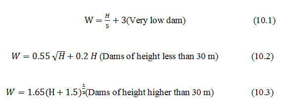
Where, W = Top width of the dam, m; H = Height of the dam, m. According to Indian standard recommendation, top width of dam should be at least 6 m.
10.2 Free Board
The free board is defined as the vertical distance between the top of the embankment and the maximum water level in reservoir. Based on the water level, the free board is classified as: (i) Normal free board and (ii) Minimum free board.
i. Normal free board: It is the difference in elevation between the top of the embankment and the normal reservoir level.
ii. Minimum free board: It is the difference in elevation between the top of the embankment and maximum water level in the reservoir.
The difference between the normal and the minimum free board is called as surcharge head. Sufficient free board must be given, while deciding the height of dam, to avoid the chances of overtopping. Recommended values of free board depending upon the nature of the spillway and height of the dam are presented in Table 10.1.
Table 10.1. Recommended values of free board
|
Nature of spillway |
Height of dam |
Free board |
|
Free |
Any |
Minimum 2 m and maximum 3 m over the maximum flood level |
|
Controlled |
Less than 60 m |
2.5 m above the top of gates |
|
Controlled |
Over 60 m |
3 m above the top of gates |
10.3 Cutoff Trench
The main function of cutoff trench in earth fill dam is to reduce the loss of stored water in the reservoir, from the seepage flow through foundation and its abutment. Furthermore it also prevents the sub surface erosion caused by piping action. The type of cut off should be decided on the basis of detailed geological investigations. It is desirable to provide positive cut off. Where this is not possible, partial cut off with or without upstream impervious blanket may be provided. In any case, adequate drainage arrangements may be provided on the downstream. The following guidelines may be adopted for design of cut off.
The cut off shall be located such that its centre line should be within the base of impervious core and should be upstream of centre line of dam.
The positive cut off should be keyed at least to a depth of 0.4 m into continuous impervious sub-stratum or non-erodible rock formation.
A minimum bottom width of 4.0 metre is recommended.
Side slopes of at least 1:1 or flatter may be provided in case of overburden while 1/2:1 and 1/4:1 may be provided in soft rock and hard rock respectively.
The back fill material for cut off trench shall have same properties as those specified for impervious core.
The cut off in the flanks on either side should normally extend up to the top of impervious core.
If cut off trench is terminated in rock formation which is weathered or have cracks, joints and crevices; and if percolation test exhibit a lugeon value of more than 10(refer IS 6066-1984), then rock foundation below the bed of cut off trench should be grouted.
Most dams, homogenous or zoned, can benefit from the construction of a cutoff in the foundation. A cutoff will reduce seepage and improve stability. Whether stable clay or other material is being used, the cutoff trench must be excavated to a depth that will minimize all possible seepage. Ideally, the cutoff trench should be dug down to solid rock that extends to great depths. If underlying rock is fissured or uneven it can be cleaned off and concreted to offer a good surface on which the clay can be laid. For larger indentations or cracks, slush grouting should be used, which is a thick slurry mix of cement and water poured and broomed into the larger cracks and fissures before any concrete is laid to fill the remaining indentations and to offer an eventual mostly flat surface. For more even surfaces with smaller cracks, a cement wash (a weaker mix of cement and water to form a creamy texture) can be brushed across a surface to seal it and again establish a mostly flat surface layer.
Generally a minimum width of 4 m is recommended however, an adequate width of cutoff trench for small dams can be determined using following formula:
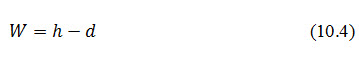
Where, W = bottom width of cutoff trench; h = reservoir head above the ground surface and d = depth of cutoff trench below ground surface.
10.4 Central Impervious Core
The core provides impermeable barrier within the body of the dam. Impervious soils are generally suitable for the core (IS 1498 -1970). The design of central impervious core of earth dam is mainly done on the basis of following points:
Tolerable limit of seepage loss
Maximum width of dam section, which permits proper construction of central impervious core
Types of material available for construction
Design criteria of proposed filter
In the design of the central impervious core, it should always be kept in mind that the shear strength of core material should be less than the embankment materials. A thinner shell provides comparatively more stability than a thick shell, because a thick shell causes more resistance to piping action and also facilitates development of cracks. The core may be located either centrally or inclined upstream. A core of 3 m width is generally used at the top of the dam. The height of the core should be at least up to 1 m above the maximum water level in the reservoir in order to prevent the seepage due to capillary action. The thickness of the core at any section shall not be less than 30% (preferably not less than 50%) of maximum head of water acting at that section.
Suitable Core Material
A soil, which has less compressibility and liquid limit, is considered as a suitable material for the construction of core. On the contrary, the soils with high compressibility and greater liquid limit, and having organic contents may be avoided, as they are prone to swelling and formation of cracks. Table 10.2 gives the list suitable materials recommended by Indian Standard (IS-8826-1978) for core construction in zoned type earthen dam.
Table 10.2. Suitable soil for core construction
|
Sl. No. |
Suitability |
Type of soil |
|
1 |
Very good |
Very well graded mixtures of sand, gravel and fines of which 15% of material (D85)are coarser than 50 mm and 50% of material (D50) are coarser than 6 mm. |
|
2 |
Good |
Well graded mixture of sand, gravel and clayey fine, D85coarser than 25 mm. Fines consisting of inorganic clay (clay with plastic index > 12) or high plastic tough clay (clay with plastic index > 20). |
|
3 |
Fair |
Fairly well graded, gravelly, medium to coarse sand with cohesion less fines, D85coarser than 19 mm, D50 between 0.5 to 3 mm. Clay of medium plasticity (clay with plastic index > 12). |
|
4 |
Poor |
Clay of low plasticity with little coarse fraction. Plastic index between 5 to 8, liquid limit > 25 Silts of medium to high plasticity with little coarse fraction having plastic index greater than 10. |
10.5 Casing or Outer Shell
The function of casing is to impart stability and protect the core. The relatively pervious materials, which are not subjected to cracking on direct exposure to atmosphere, are suitable for casing. Top width of dam should be provided as 4.5 m (minimum). The berms may be provided for the dam, which are more than 10 m in height. Minimum berm width may be kept as 3m.The upstream and downstream side slopes of the embankment are determined based on the characteristics of the available materials, foundation condition, dam height and type of the dam. The recommended upstream and downstream side slopes, given by Terzaghi, are shown in Table 10.3.
Table 10.3. Recommended side slopes of earthen dam

10.6 Internal Drainage System
To ensure safety of dam, it is very important to handle the seepage water in the dam so as to maintain the original particles of soils in their place. The measures commonly adopted for safe disposal of seepage water through embankment dams are:
Inclined or vertical filter (chimney filter)
Horizontal filter
Rock toe
Toe drain
As far as possible locally available sand, gravel etc. should be used for the purpose. Inclined or vertical filter is provided just on downstream slope of the core. Its thickness is kept at least 1.0 m. Horizontal filter collects the seepage from chimney filter and foundation, and carries to the rock toe and toe drain. Its thickness is kept to a minimum of 1.0 m. The standard filter criterion between filter and adjoining soil (casing or foundation) should be satisfied. In case of dam portions, where the head of water is 3 m or less it is not required to provide chimney filter or horizontal filter. Adequate toe protection shall however be provided. The height of rock toe is generally provided as 0.2 H, where H is the height of embankment. However minimum height of rock toe is kept as 1.0 m. Rock toe is not necessary where height of embankment is 3 m or less.
The toe drain is provided at the downstream toe of the earth dam to collect seepage from horizontal filter, rock toe and through foundation; and to discharge it away from the dam by suitable surface or sub surface drains. The section of the drain should be adequate enough to carry seepage. The bed of toe drain should be given a suitable slope to direct the seepage to natural drains. Depth of toe drain is usually provided as 1.5 m with minimum bottom width of 1.0 m and side slopes of 1:1.The filter material should satisfy the following criteria with the base material:
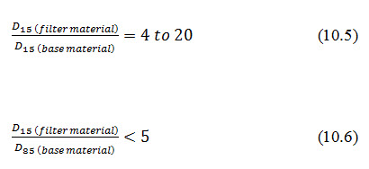
A filter that satisfies the above criteria may yet fail if it has an excess or lack of certain sizes or is not uniformly graded. In such cases, the following criteria must be fulfilled:
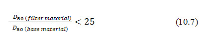
The gradation curve of the filter material should be nearly parallel to the gradation curve of the base material.
10.7Slope Protection
Upstream slope: The upstream slope protection is ensured by providing riprap. For design of riprap, IS 8237-1985 may be referred. A minimum of 300 mm thick riprap over 150 mm thick filter layer may be provided upto the top of the dam.
Downstream slope: The downstream slope protection is ensured by turfing or riprap. It is usual practice to protect the downstream slope from rain by providing suitable turfing on the entire downstream slope from top to toe. For details of downstream slope protection, IS 8237-1985 may be referred.
10.8 Surface Drainage
For surface drainage of downstream slope, a system of open paved drains (chutes) along the sloping surface terminating in the longitudinal collecting drains at the junction of berm and slope shall be provided at 50 m centre to centre to drain the rain water. The section of drain may be trapezoidal having depth of 30 cm. From longitudinal collecting drain, the rain water is carried through 15cm diameter pipes placed at 50 m centre to centre into paved chutes on the downstream slope. Where no berm has been provided, the open paved drains should terminate in the downstream rock toe or toe drain.
10.9 Impervious Blanket
The horizontal impervious blanket is provided to increase the path of seepage when full cutoff is not practicable in pervious foundation. The impervious blanket shall be connected to the core of the dam. To avoid formation of crack, the material should not be highly plastic. A 300mm thick layer of random material over the blanket is recommended to prevent cracking due to exposure to atmosphere. As a general guideline, impervious blanket with a minimum thickness of 1.0 m and a minimum length of 5 times the maximum water head measured from upstream toe of core may be provided.
10.10Design of Spillway
Estimation of peak flood is required for spillway design (which is explained in subsequent chapters), the dimensions and physical characteristics of which are extremely important. If a suitable spillway of sufficient size is not available at a particular site, or would prove to be too expensive, it is advisable to move on to a better alternative site where spillway conditions can be met. On larger catchments (>5-8 km2), rock spillways are virtually essential. Therefore, good solid rock of adequate width must be available for all but the smallest dams. As a very rough guide at this stage and subject to re-assessment at the detailed design stage, a minimum width of 15 m at 1.5 m freeboard for a dam on a catchment of around 5 km2may prove suitable. However, advice from local engineers and experienced local people should be sought if hydrological data and/or design charts are not available. It is probable that more earth dams in southern and western African suffer problems through poor spillway design than for any other reason. If there is insufficient rock, the site should not be used for a dam.
Grass spillways, whether cut or natural, are really only suited to small catchments (i.e. up to 5 km2) and low velocity flows (certainly below 1 m/s) and even then may require continual maintenance throughout the life of the dam to prevent erosion from becoming too serious a problem. The ability of vegetation or soil to resist erosion is limited and maintenance of an even surface and uniform cover is very important. The stability of the channel as a whole will depend upon the stability of the most sparsely covered section and it is therefore wise to establish a good creeping grass cover throughout.
The grass cover condition will directly affect the channel’s roughness coefficient, which in turn depends upon flow. A low flow will meet high resistance while a high flow will flatten the grass and thus meet much lower resistance. Maximum allowable non-erosive velocities are highest in grass spillways that have been planted to shorter creeping varieties such as kikuyu, couch and star grasses. These can establish a uniform low cover offering minimum resistance to flow and maximum protection to the soil below. However, where even normal flows are expected to constitute an erosion risk (when the flow is expected to continue during the dry season and/or over a period of several months or more), a drop-inlet overflow spillway should be planned for and located at the opposite end of the embankment to the main spillway and at an elevation on the upstream side of the dam slightly lower (usually 50-100 mm) than full supply level.
A mechanical spillway is provided in the embankment type pond to let out water from the storage in a regulated manner. To protect the embankment from over topping due to unexpected inflows into the storage, an emergency spillway is located on one end of the embankment. The bottom elevation of the emergency spillway should be maximum flood level expected for the selected frequency of runoff into the pond.
The dimensions of the emergency spillway for farm pond are determined from the runoff through it. If there is adequate capacity above the spillway for storage, a reduction in the peak flow for the design of the emergency spillway channels are designed on the basis of weir formula given earlier. Permanent structures are constructed to serve as mechanical spillways from farm pond. The drop spillway and the drop-inlet are the two structures which are commonly used. The drop spillway can handle higher discharges than the drop-inlet. However the drop inlets provide a better control over the water stored in the pond. The design and construction of these structures are same as in gully control structures. Some minor modifications in these structures are done when they are used in farm ponds. The drop structures constructed in the embankment of the pond is referred to as surplus weir. Sometimes a row of vertical pillars on the crest are constructed. When storage of additional water is desired, soil is filled between these pillars so as to block the water. The drop inlet spillway is also constructed as a simple pipe culvert, provisions of a control valve or a sliding head gate is provided in order to regulate the outflow of water. In case of ponds constructed for aquaculture purposes, outlet structures are needed for draining out the water as required.
Example 10.1 The peak rate of runoff expected from the catchment area of a tank is 4 cum. per second. Assuming no temporary storage, find the length of the surplus weir, if the depth of flow over is not to exceed 0.75m.
Solution: Using Francis formula for discharge through broad crested weirs
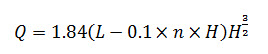
Where, Q = discharge, m3/s; L = length of weir, m; N= number of end contractions; and H = head of flow, m.
4 =1.84 (L- 0.1×2×0.75) 0.753/2
L=3.5 m (Ans)
10.11 Basic Design Requirements
Some of the basic design requirements are discussed below.
10.11.1 Safety against Overtopping
Sufficient spillway capacity should be provided to prevent overtopping.
The free board should be sufficient to prevent overtopping by waves. The minimum free board of 1.5m should be provided.
The free board should be sufficient to take into account the settlement of embankment and foundation.
10.11.2 Stability Analysis
The design of small embankment dam sections may be divided into the following three categories based upon the height of the embankment in its deepest portion.
i. where the height of embankment is 5m or less
ii. where the height of embankment is 10 m or less, but more than 5 m
iii. where the height of embankment is 15 m or less, but more than 10 m
For small dams under category (i) and (ii) above, the stability analysis may not be necessary. The minimum top width may be kept as 4.50 m.
However the designer with his experience and judgement may decide the adequate side slopes where special technical or economic considerations may have to be taken into account.
Stability analysis may be carried out in accordance with IS 7894-1975 based upon the detailed foundation and borrow area investigation and laboratory testing if the soil strata below the dam seat consist of weak foundation and / or the height of embankment is more than 10 m. Weak foundation conditions include fissured clay, expansive soils, shale’s, over-consolidated highly plastic clays, soft clays, dispersive soils etc. within the substratum in the dam seat.
Main problem of silt and clay foundations is stability. In addition to the obvious danger of bearing failure of foundations of silt and clay, the design must take into account effect of saturation of the foundations of the dam and appurtenant works by the reservoir.
Methods of Treatment
(a) To remove soils of low shearing strength
(b) To provide drainage of foundation to permit increase of strength during construction
(c) To reduce magnitude of average shearing stress along potential surface of sliding by flattening slopes of embankment
(d) Pockets of material substantially more compressible or lower in strength than the average, are usually removed.
The most practicable solution for foundation of saturated fine-grained soils is to flatten the slopes of embankment. Soils of low density are subjected to large settlements when saturated by the reservoir, although these soils have high dry strength in natural state. If proper measures are not taken to control excessive settlement, failure of dam may occur by differential settlement and foundation settlement .The required treatment of low density foundation would be dictated by the compression characteristics of the soil. Foundation consolidation will be achieved during construction.
10.11.3 Seepage Control and Safety against Internal Erosion
The seepage through the dam embankment and foundation should be such as to control piping, erosion, sloughing and excessive loss of water. Seepage control measures are required to control seepage through dam and foundation.
Zoning
If only one type of suitable material is readily available nearby, a homogeneous section is generally preferred. When the material available is impervious or semi pervious in nature, then a small quantity of pervious material is required as casing for protection against cracking. On the other hand if it is pervious, a thin impervious membrane is required to form a water barrier.
10.11.4 Stability at Junctions
Junctions of embankment dam with foundation, abutments, and masonry structures like overflow, non-overflow dams and outlets need special attention with reference to one or all of the following criteria.
Good bond between embankment dam and foundations
Adequate creep length at the contact plane
Protection of embankment dam slope against scouring action
Easy movement of traffic
Keywords: Dam components, Suitable core, Surface drainage, Spillway, Stability analysis
Suggested Readings
Suresh, R. 2002. Soil and Water Conservation Engineering. Standard publishers distributors
www.fao.org/docrep/012/i1531e/i1531e01.pdf
IS 12169:1987 Criteria for design of small embankment dams.
IS 8237:1985 Code of practice for protection of slope for reservoir embankment.
IS 9429:1999 Code of practice for drainage system for earth and rock fill dams.
IS 8414:1977 Guidelines for design of under seepage control measures for earth and rock fill dams.
IS 6066:1994 Pressure grouting of rock foundations in river valley projects - Recommendations (Second revision).
IS 10635:1993 Guidelines for freeboard requirement in embankment dams.
IS 1498:1970 Classification and identification of soils for general engineering purpose.
IS 7894:1975 Code of practice for stability analysis of earth dams?
Last modified: Monday, 3 February 2014, 9:43 AM