Site pages
Current course
Participants
General
MODULE 1.
MODULE 2.
MODULE 3.
MODULE 4.
MODULE 5.
MODULE 6.
MODULE 7.
MODULE 8.
MODULE 9.
MODULE 10.
MODULE 11.
MODULE 12.
LESSON 21. Design of T- Beams
21.1 INTRODUCTION
Three main types of problem may be put in case of T-beams.
Type I. In this type the following information is given:
(i) The dimension of the section
(ii) Area of steel reinforcement
(iii) The maximum permissible stresses in concrete and steel.
It is required to determine the moment of resistance of the section.
Procedure to solve: The solution of this type of problem involves the steps given below.
(i) Calculate the position of the actual neutral axis by equating the moment of the compressive area of concrete to the moment of equivalent concrete area of steel in tension about the N.A. Assuming that the neutral axis lies within the flange
\[\left[{\frac{{{b_f}.{n^2}}}{2}}\right]= m.{A_{st}}\left({d-n}\right)\]
If n from this expression works out to be more than the thickness of the flange (\[{d_f}\], the N.A. will be in the web and it will be necessary to re-work it out by use of expression.
\[{b_f}.{d_f}\left({n-\frac{{{d_f}}}{2}}\right) = m.{A_{st}}\left({d-n}\right)\]
(ii) Find the position of critical neutral axis (nc) given by
\[\frac{{{n_{st}}}}{d}=\frac{{m.{\sigma _{cbc}}}}{{m.{\sigma _{cbc}}+{\sigma _{st}}}}\]
(iii) If the actual neutral axis lies above the critical N.A., the section is under-reinforced and steel attains its maximum permissible value of t=σst first. The corresponding stress in concrete is calculated from the relation.
\[c=\frac{1}{m}.\frac{n}{{\left({d - n}\right)}}=\frac{{{\sigma _{st}}}}{m}.\frac{n}{{(d - n)}}\]
(i) If the neutral axis lies in the flange the moment of resistance of the section is given by
![]()
If the N.A. lies in the web, the moment of resistance is given by
![]()
Where 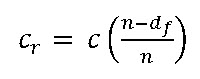
And ![]()
(v) If the actual N.A. lies below the critical N.A., the section is over-reinforced and concrete attains its maximum permissible stress of \[c={\sigma _{cbc}}\] first.
The moment of resistance of the section is given by
\[{\rm{M\_r=b\_f}}{\rm{.d\_(f )(c + c\_s)/2}}\]
(where c = ).
Type II. In this type the following information is given:
The dimensions of the section.
Area of reinforcement
The maximum bending moment to which the section is subjected to.
It is required to determine the stresses developed in concrete and steel.
Procedure to solve: The solution of this type of problem involves the steps given below.
(i) Calculate the position of the neutral axis by equating the moment of equivalent areas about the neutral axis. Assuming that N.A. lies in flange, we get
\[\frac{{{b_f}.{n^2}}}{2} = m.{A_{st}}(d - n)\].
If the value of n, obtained from this equation is more than the thickness of flange\[{d_f}\], the N.A. falls in web and it will be necessary to re-work it out by use of expression.
\[{b_f}.{d_f}\left({a-\frac{{{d_f}}}{2}}\right)=m.{A_{st}}\left({d - n}\right)\]
(ii) Equate the moment of resistance of the beam to the external bending moment (M) and calculate the compressive stress developed in concrete by the relevant equation.
(a) If N.A. lies within flange, we have
\[{b_f}.n.\frac{c}{2}\left({d-\frac{n}{3}}\right)=M\]
(b) If N.A. lies in web, we have
\[{b_f}.{d_f}\frac{{(c+{c_s})}}{2}\times a=M\]
Where \[{c_s}=c\left({\frac{{n-{d_f}}}{n}}\right)\]
And ![]()
(iii) Having calculated c, the stress developed in steel can be worked out by the relationship.
\[t =m.c\left({\frac{{d - n}}{n}}\right)\]
Type III. In this type of problem, the maximum permissible stress in concrete and steel and the bending moment (M) to which the section is subjected to are given and it is required to design the section.
Procedure to solve: The solution of this type of problem involves the steps given in ------------ chapter.
Example 20.1 A T-beam has an effective width of flange as 1750 mm. The thickness of the flange in 150 mm and the beam is reinforced with 35 sq. cm of tensile steel placed at a depth of 500 mm below the top of flange. If the width of web is 300 mm, find the position of the neutral axis of the beam. Take m = 15.
Solution: Assuming that the neutral axis of the beam is situated below the flange and equating the moment of the equivalent areas about N.A., we get
\[{b_f}.{d_f}\left({n-{d_f}}\right) = m.{A_{st}}(d - n)\]
or ![]()
Which Gives \[n = 145.83mm\]
This shows that our assumption that n lies below the flange is wrong and hence the correct value of the actual neutral axis will be given by the expression.
\[\frac{{{b_f}.{n^2}}}{2} = m.{A_{st}}(d - n)\]
or \[\frac{{1750{n^2}}}{2}=15\times 3500(500 - n)\]
or \[{n^2}+60n-30000=0\]
Which Gives \[n = 145.78\]
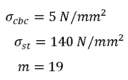
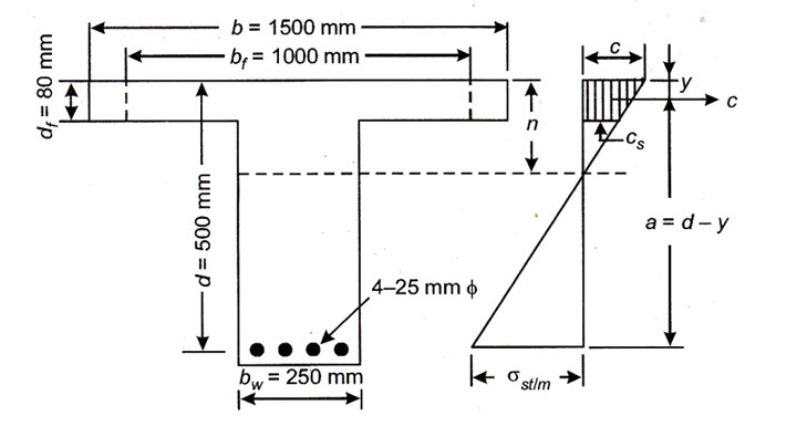
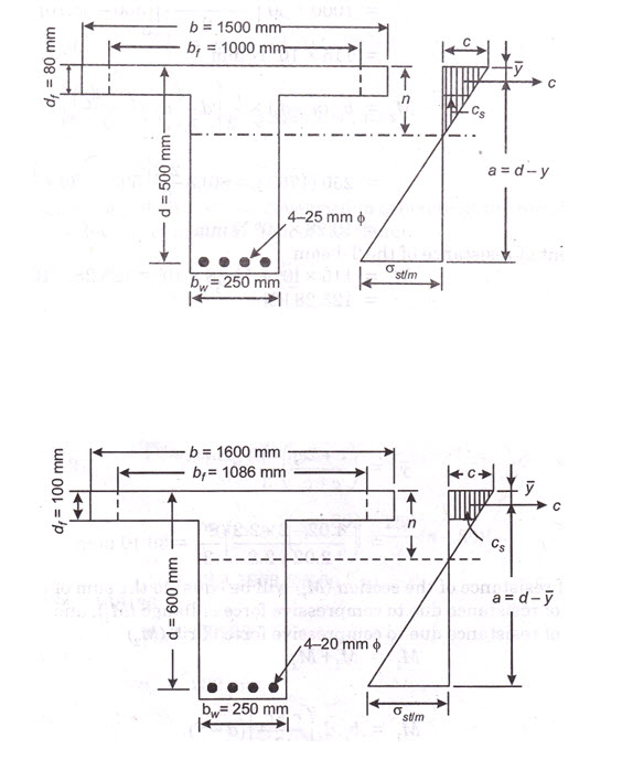
Example 20.2 An isolated T-beam simply supported over a span of 6 m has a flange width of 1500 mm. The thickness of the flange is 80 mm and the beam has an effective depth of 500 mm up to the centre of tensile reinforcement which consists of 4 Nos. of 25 mm. dia. bars. Calculate the moment of resistance of the section neglecting compression resistance of the area of web above the neutral axis. The width of web is 250 mm.
Adopt:
Solution The effective width of flange for an isolated T-beam is given by
\[{b_f}=\frac{{{l_0}}}{{\left({\frac{{{l_0}}}{b}}\right)+4}}+{b_w}=\frac{{6 \times1000}}{{\frac{{6\times1000}}{{1500}}+4}}+250=1000mm.\]
\[{A_{st}}=4\times\frac{\pi}{4}\times{\left({25}\right)^2}=1963.5m{m^2}\]
To find N.A., equating the moments of equivalent areas about N.A. assuming that the neutral axis falls outsides the flange, we get
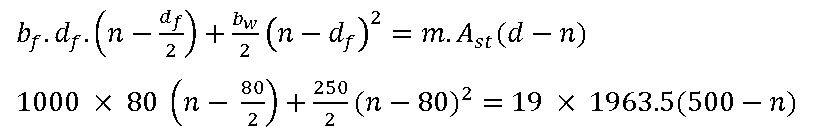
\[{\rm{b\_f}}{\rm{.d\_f (n - d\_f/2) = m}}{\rm{.A\_st (d - n)}}\]
or \[1000\times80\left({n-\frac{{80}}{2}}\right)=19\times1963.5(500 - n)\]
Which gives \[n =186.33mm\]
The depth of critical neutral axis is given by
\[\frac{{{n_c}}}{d}=\frac{{m.{\sigma _{cbc}}}}{{m.{\sigma _{cbc}} + m.{\sigma _{st}}}} = \frac{{19 \times 5}}{{19\times 5 + 140}} = 0.404\]
\[{n_c}=0.404\times d=0.404\times500=202mm\]
Since the actual N.A. lies above the critical N.A., the stress in steel reaches the maximum permissible value of \[t={\sigma _{st}}=140N/m{m^2}\] first. The corresponding stress in concrete is given by
\[c=\frac{{{\sigma _{st}}}}{m}.\frac{n}{{d - n}}=\frac{{140}}{{19}}\times\frac{{186.33}}{{(500-186.33)}}= 4.38N/m{m^2}\]
and the stress in concrete at the bottom of flange is given by
\[{c_s}=\frac{{c(n - {d_f})}}{n} =\frac{{4.38(186.33 - 80)}}{{186.33}}=2.2N/m{m^2}\]
\[\bar y = \left({\frac{{c + 2{c_s}}}{{c + {c_s}}}}\right)\frac{{{d_f}}}{3}=\left({\frac{{4.38+2\times2.50}}{{4.38 +2.50}}}\right)\frac{{80}}{3}=35.36mm\]
Lever arm of the T-beam \[a=d-\bary=500-36.36=463.64mm\]
The moment of resistance of the T-beam
\[{M_r}={\rm{TotalcompressionxLeverarm}}={b_f}.{d_f}\frac{{c+{c_s}}}{2}\times a\]
\[{M_r}=1000x80\left({\frac{{4.38 + 2.50}}{2}}\right)x463.64=127.6x{10^6}Nmm=127.6kNm\]
Alternatively, the moment of resistance is also given by
\[{M_r}={\rm{TotalcompressionxLeverarm}}={\sigma _{st}}.{A_{st}}xa\]
\[= 140 \times1963.5\times 463.64=127.6\times{10^6}Nmm=127.6kNm\]
Example 20.3 Solve example after taking the compressive force in web in to account.
Solution. To find the neutral axis: Equating the moment of the equivalent areas about N.A.,
we get,
Which Gives \[n=176.39\]
As already Calculated \[{n_c}=202mm\]
Since the actual N.A. lies above the critical N.A. the stress in steel reaches its maximum permissible value of \[t = {\sigma _{st}} = N/m{m^2}\] first. The corresponding stress in concrete at top of flange is given by concrete at the bottom face of flange is given by
\[{c_s} = \frac{{{\sigma _{st}}}}{m}.\frac{n}{{d-n}}=\frac{{140}}{{19}}\times\frac{{176.39}}{{(500-176.39)}}=4.02N/m{m^2}\]
And the stress in concrete at the bottom face of flange is given by
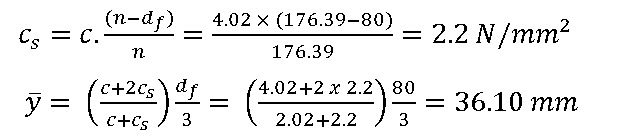
The moment of resistance of the section (Mr) will be equal to the sum of the following.
(i) Moment of resistance due to compressive force of flange (M1); and
(ii) Moment of resistance due to compressive force of rib (M2)
\[{M_1}={M_1}+{M_2}\]
now,\[{M_1} = {b_f}.{d_f}\left( {\frac{{c +{c_s}}}{2}}\right)(d-\bar y)\]
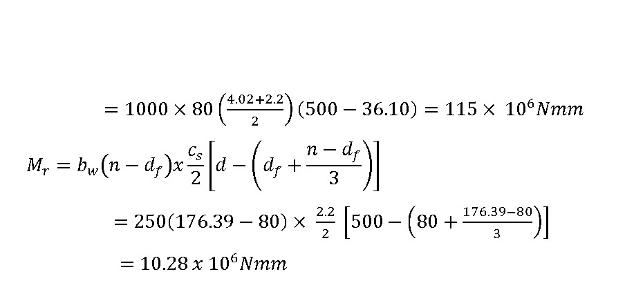
The moment of resistance of the T-beam
\[{M_r}=115x{10^6}+10.28x{10^6}=125.28x{10^6}Nmm=125.28kNm\]
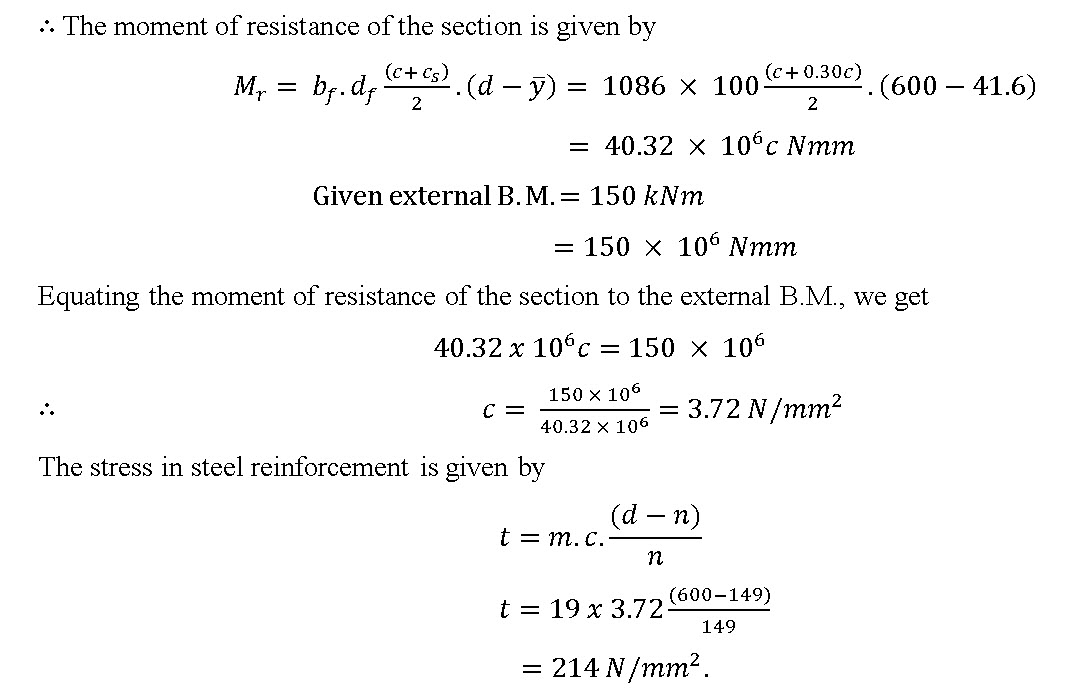
Example 20.4 The flange of an isolated T-beam is 100 mm thick and 1600 mm wide. Its web is 250mm wide and the effective depth of the beam up to the centre of tensile reinforcement is 600 mm. The tensile reinforcement consists of 4 Nos. 20 mm dia. bars. The beam is simply supported over a span of 7 m. If the beam section is subjected to a bending moment of 150 kNm, calculate the stresses developed in concrete and steel reinforcement. Take m = 19.
Solution The effective width of flange of an isolated T-beam is given
\[{b_f} = \frac{{{l_0}}}{{\left( {\frac{{{l_0}}}{b}} \right) + 4}} + {b_w} = \frac{{7000}}{{\frac{{7000}}{{1600}} + 4}} + 250 = 1086mm.\]
\[{A_{st}} = 4 \times \frac{\pi }{4} \times {\left( {20} \right)^2} = 1256m{m^2}\]
Equating the moment of equivalent area about the neutral axis (neglecting the compression in web), we get
\[{b_f}{d_f}.\left( {n - \frac{{{d_f}}}{2}} \right) = m.{A_{st}}(d - n)\]
or \[1086{\rm{x}}100{\rm{}}\left( {n - \frac{{100}}{2}} \right) = 19x1256(600 - n)\]
which gives \[n = 149mm\]
Let c, be the maximum compressive stress developed in concrete at the top of the flange and be the compressive stress developed at the bottom of the flange.
\[{c_s} = c.\frac{{\left( {n - {d_f}} \right)}}{n} = c.\frac{{\left( {149 - 100} \right)}}{{149}} = 0.33c\]
\[\bar y = \left( {\frac{{c + 2{c_s}}}{{c + {c_s}}}} \right)\frac{{{d_f}}}{3} = \left( {\frac{{c + 2 \times 0.33c}}{{c + 0.33c}}} \right)\frac{{100}}{3} = 41.6mm\]
The moment of resistance of the section is given by
Last modified: Saturday, 5 October 2013, 8:48 AM