Site pages
Current course
Participants
General
MODULE 1.
MODULE 2.
MODULE 3.
MODULE 4.
MODULE 5.
MODULE 6.
MODULE 7.
MODULE 8.
MODULE 9.
MODULE 10.
MODULE 11.
MODULE 12.
LESSON 23. Bond and Development Length
23.1 INTRODUCTION
The fact which makes it possible to combine steel and concrete is that concrete on setting grips fast the embedded steel rods. Thus when the R.C.C. member is loaded the transference of force between concrete and embedded steel reinforcements takes place only virtue of the grip, adhesion or bond between the two materials. The bond between concrete and steel must be sufficient to make them act jointly. In case the grip between the two materials is not perfect, an R.C. beam when loaded will fill as the steel reinforcement on account of the imperfect bond will slip and will not contribute to resist any stresses developed in the beam. The grip depends upon the mix and quality of the concrete, surface and shape of the bars, the length of embedment and the cover of concrete on steel reinforcement.
To achieve increased bond between steel and concrete the following factors should be kept in view:
(i) Use rich mix of concrete
(ii) The compaction and curing of concrete should be perfect
(iii) Provide adequate cover to steel reinforcement
(iv) Use rough surface steel bars. The bars with smooth or polished surface will not be able to provide adequate frictional resistance for the purpose of perfect grip.
(v) Use deformed or twisted bars.
23.2 DEVELOPMENT LENGTH
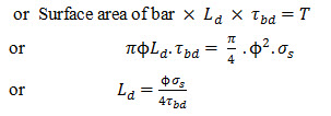
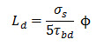
The check for satisfying the requirement of permissible bond stress specified in the earlier code has now been replaced by the concept of development length. It is obvious that bar with sufficient embedment in concrete cannot be pulled out. Development length is the minimum length of bar which must be embedded in concrete beyond any section to develop by bond (between the concrete and steel), a force equal to the total tensile force in the bar at that section. Development length is represented by a symbol Ld and it is expressed in terms of the diameter of the bar.
Refer Fig. 23.1. Let a mild steel reinforcing bar of diameter ( ) be embedded in a concrte block. Let T be the pull or tensile force applied to the bar at its free end and Let Ld be the minimum length of embedment of the bar in the concrete block so as to withstand the tensile force without any slippage.
If be the stress developed in the steel reinforcement bar due to the T. The pull T can also be written as
![]()
The tensile force due to the pull has to be transmitted to the concrete by bond stress in the embedment length Ld. Bond stress is the local longitudinal shear stress per unit of bar surface. Bond stress can also be defined as the shear force per unit of nominal surface area of a reinforcing bar acting parallel to the bar on the interface between the bar and the surrounding concrete. The magnitude of bond stress varies along the length of the bar. Its value will be maximum at lower face of block and minimum at end of bar in concrete. Based on experimental evidence it is seen that value of Ld derived based on average bond stress works out to be safe.
Let be the average bond stress developed in concrete due to the pull in the bar. achieve condition of no slippage of bar and equilibrium
Force developed in bar in concrete = Applied pull
Code has specified values of average permissible bond stress for plain bar in tension for different grades of concrete which has been reproduced in Table 23.1 for ready reference.
TABLE 23.1 Permissible bond stress (Average) for plain bars in tension.
|
Grade of concrete |
M 10 |
M 15 |
M 20 |
M 25 |
M 30 |
M 35 |
M 40 |
|
Permissible stress in bond (\[{\tau _{bd}}\]) \[inN/m{m^2}\] |
---- |
0.6 |
0.8 |
0.9 |
1.0 |
1.1 |
1.2 |
Note 1. The bond stress given above shall be increased by 25 per cent for bars in compression.
Note 2. In the case of deformed bars conforming to IS : 1139 -1966 and IS: 1786 – 1979, the bond stress given in Table 23.1 may be increased by 40%.
23.3 DEVELOPMENT OF STRESS IN REINFORCEMENT
For ensuring full development of the calculated tension or compression in any bar at any section, it is necessary that the bar under consideration should extend on each side of the section by appropriate length which is termed as development length. The formula for calculating development length of bars in tension and compression for mild steel and HYSD bars are given below:
(i) Development length of bars in tension. The development length Ld for bars in tension is given by
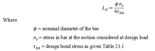
Note. The development length includes anchorage values of hooks in tension reinforcement.
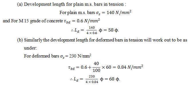
It may be noted that the above expression for development length is similar to the one for bond length as given in earlier code, except change of symbol in the relationship. Based on the above formula the values of for plain and deformed bars for M 15 grade of concrete can be worked out as under:
(a) Development length for plain m.s. bars in tension :
For plain m.s. bars
The development length of mild steel bars and HYSD bars for different grades of concrete are given Table 23.2
TABLE 23.2 Development lengths for M.S and HYSD bars in tension
|
Grade of concrete |
Mild steel bars ( \[{\sigma _{st}}=140N/m{m^2}\] ) |
HYSD bars ( \[{\tau _{st}}=230N/m{m^2})\] |
||
|
\[{\tau _{bd}}\] in \[N/m{m^2}\] |
Ld |
\[{\tau _{bd}}\] in \[N/m{m^2}\] |
Ld |
|
|
M 15 |
0.6 |
58 \[{\rm{}}\phi\] |
0.84 |
68 \[{\rm{}}\phi\] |
|
M 20 |
0.8 |
44 \[{\rm{}}\phi\] |
1.12 |
52 \[{\rm{}}\phi\] |
|
M 25 |
0.9 |
39 \[{\rm{}}\phi\] |
1.26 |
46 \[{\rm{}}\phi\] |
|
M 30 |
1.0 |
35 \[{\rm{}}\phi\] |
1.40 |
41 \[{\rm{}}\phi\] |
|
M 35 |
1.1 |
32 \[{\rm{}}\phi\] |
1.54 |
37 \[{\rm{}}\phi\] |
|
M 40 |
1.2 |
29 \[{\rm{}}\phi\] |
1.68 |
34 \[{\rm{}}\phi\] |
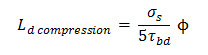
(ii) Development length for bars in compression. It is simpler to pull a bar out of concrete than to push it inside. The Code accordingly permits 25 percent increase in the value permissible bond stress for bars in compression. Based on the above, the development length for bars in compression is given by
23.4 ANFHORAGE FOR REINFORCEMENT BARS
The development length of bars as obtained from the above formula can be provided in the form of straight length or it may be partially straight and partially anchored. The anchorage is normally provided in the form of bends and hooks.
(i) Anchoring bars in tension: In case of deformed bars in tension, the development length is provided straight without end anchorage. In case of plain bars ends hooks are normally provided for anchorage.
The anchorage value of bend shall be taken as 4 times the diameter of the bar for each 45˚ bend subject to a maximum of 16 times the diameter of the bar. The dimensions of a standard hook and a standard 90˚ bend are shown in Fig. 23.2). The value of k to be adopted depends upon the type of steel. Its value as per code is as under.
|
|
Type of steel |
Min. value of k |
|
(i) |
Mild steel |
2 |
|
(ii) |
Cold worked steel |
4 |
The anchorage value of a standard hook and a standard bend are taken as 16 and 8 respectively.
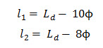
Let be the required value of development length for a reinforcing bar and and be the straight lengths required when the end bar anchorage are provided in the form of a semi-circular hook and a right angle bend hook respectively. The value of and in term of can be written as
(ii) Anchoring bars in compression: The anchorage length of straight bar in compression shall be equal to the development length of bar in compression as obtained from the formula
The end of a bar in compression require no special anchorage.
(iii) Anchoring shear reinforcement: The shear reinforcement can be provided in the form of inclined bar as well as stirrups.
(a) In case of inclined bars: The development length shall correspond to development length of bars in tension allowing for hook and bends when provided and measures as under:
(1) In tension zone; from the end of inclined portion of bars.
(2) In compression zone; from the mid-depth of the beam..
(b) In case of stirrups: In case of stirrups complete development length and anchorage shall be deemed to have been provided when
(i) the bar is bent through an angle of at least 90˚ round a bar of at least its own diameter and is continued beyond the end of the curve for a length of at least eight diameters or
(ii) when the bar is bent through an angle of 135˚ and is continued beyond the end of the curve for a length of at least six bar diameters or
(iii) when the bar is bent through an angle of 180˚ and is continued beyond the end of the curve for a length of at least four bar diameters.
23.5 TO DECIDE THE CURTAILMENT OF BARS
A repeated reference has been made in this chapter and in the chapter on shear regarding bent up bars. To find out the point at which the bars at mid-span of a simply supported beam loaded with uniformly distributed load, can be safely curtailed or bent up, proceed as below:
Area of steel at mid span of a beam is obtained by using the formula
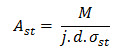
Assuming the beam to be of constant depth, the denominator i.e., j.d. may be taken to be a constant, say K
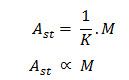
or
Or the number of bars required at any section of the beam the bending moment at the section.
Let Mc and nc, represent the bending moment and the number of bars, (provided to resist the bending moment) respectively at the mid span of the beam.
Let Mx and nx represent the bending moment at any distance x from the mid-span and the number of the bars which can be curtailed. The number of bars left at section x to resist the B.M. of
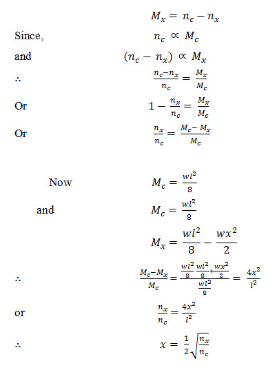
This equation gives us a relation between the number of bars which can be curtailed or bent up at any distance x, from the mid span of the beam, so that the beam remains safe from considerations of bending moment.
Last modified: Saturday, 5 October 2013, 9:02 AM