Site pages
Current course
Participants
General
MODULE 1.
MODULE 2.
MODULE 3.
MODULE 4.
MODULE 5.
MODULE 6.
MODULE 7.
MODULE 8.
MODULE 9.
MODULE 10.
MODULE 11.
MODULE 12.
LESSON 24. Basic Rules for Design of Beams and Slabs
24.1 INTRODUCTION
The details given below are based on the recommendations made in IS: 456-1978.
24.2. EFFECTIVE SPAN
(a) For simply supported beam and slab: The effective span of a simply supported beam or slab is taken as the distance between the centre to centre of support or the clear distance between the supports plus the effective depth of the beam of slab whichever is smaller.
(b) For continuous beam or slab: In case of a continuous beam or slab, where the width of the support is less than 1/12 the clear span, the effective span shall be worked out by following the rule given in (a) above.
In case the supports are wider than 1/12 of the clear span or 600 mm whichever is less, the effective span shall be taken as under.
(i)For end span with one end fixed and the other continuous or for intermediate spans, the effective span shall be the clear span between supports.
(ii) For end span with one end free and the other continuous, the effective span shall be equal to the clear span plus half the effective depth of the beam or slab or the clear span plus half the width of the discontinuous support, whichever is less.
Note: In case of span with roller or rocker bearings the effective span shall always be the distance between the centres of bearings.
(c) Frames. In the analysis of a continuous frame, effective span shall be taken as the centre to centre distance between the supports.
24.3 CONTROL OF DEFLECTION/DEPTH OF BEAMS AND SLABS
It is necessary to impose a check on the magnitude of deflection in a structural member with a view to ensure that the extent of deflection does not adversely affect the appearance or efficiency of the structure or finishes or partition etc. Control on deflection is also necessary to prevent structural behavior of the member being different from the assumption made in the design. As per Code for beams and slabs, the vertical deflection limits may be assumed to be satisfied, provided that the span to depth ratio are not greater than the values obtained as below.
(a) Basic values of span to effective depth ratios for spans up to 10m.
(i) Cantilever 7
(ii) Simply supported 20
(iii) Continuous 26
(b) For spans above 10m, the values in (a) may be multiplied by 10/span in metres, except for cantilever in which case deflection calculations should be made.
(c) Depending on the area and the type of steel for tension reinforcement the values in (a) or (b) shall be modified as per Fig.24.1.
(d) Depending on the area of compression reinforcement the values of span to depth ratio shall be further modified as per Fig.24.2.
(e) For flanged beams, the values of (a) or (b), be modified as per Fig.24.3 and the reinforcement percentage for use in Fig. 24.1 and Fig. 24.2 should be based on area of section equal to .
Note 1. For slabs spanning in two directions, the shorter of the two spans should be used for calculating the span to effective depth ratios.
Note 2. For two-way slabs of small spans (up to 3.5m) with mild steel reinforcement, the span to overall depth ratios given below may generally be assumed to satisfy vertical deflection limits for loading class upto 3000 N/m2.
Simply supported slabs 35
Continuous slabs 40
For high strength deformed bars, of grade Fe 415, the values given above should be multiplied by 0.8.
24.4 SLENDERNESS LIMITS FOR BEAMS
To ensure lateral stability, a simply supported or continuous beam shall be so proportioned that the clear distance between the lateral restraints does not exceed 60 b or ![]() whichever is less, where d is the effective depth of the beam and b, the breadth of the compression face mid-way between the lateral restraints.
whichever is less, where d is the effective depth of the beam and b, the breadth of the compression face mid-way between the lateral restraints.
For a cantilever, the clear distance from the free end of the cantilever to the lateral restraint shall not exceed 25b or ![]() whichever is less.
whichever is less.
24.5 REINFORCEMENT IN BEAMS
24.5.1 Tension Reinforcement
(i) Minimum reinforcement: The minimum area of the tension reinforcement in beams shall not be less than that given by the following expression
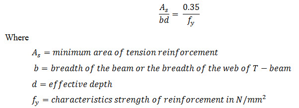
(ii) Maximum reinforcement: The maximum area of tension reinforcement in a beam shall not exceed 0.04 b D. Where D is the overall depth of the beam.
24.5.2 Compression Reinforcement
The maximum area of compression reinforcement in a beam shall not exceed 0.04 bD. For effective lateral restraint, the compression reinforcement in beams shall be enclosed by stirrups.
24.5.3 Side Face Reinforcement
Where the depth of the web in a beam exceeds 750 mm, side face reinforcement shall be provided along the two faces. The total area of such reinforcement shall be not less than 0.1 per cent of the web area and shall be distributed equally on the two faces at a spacing not exceeding 300 mm or web thickness whichever is less.
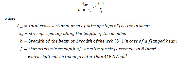
24.5.4 Minimum Area of Shear Reinforcement
Minimum shear reinforcement in the form of stirrups shall be provided that
24.5.5 Maximum Spacing of Sheer Reinforcement
Maximum spacing of shear reinforcement measured along the axis of the member shall be as under
|
(i) |
For vertical stirrups |
0.75d or 450mm whichever is less |
|
(ii) |
For inclined stirrups at 45˚ |
d or 450mm whichever is less |
24.6 REINFORCEMENT IN SLABS
24.6.1 Minimum Reinforcement
The area of reinforcement in either direction in slabs should not be less than 0.15 per cent of the total cross-sectional area in case mild steel bars are used as reinforcement. In case of high strength deformed bars of welded wire fabric, this value can be reduced to 0.12 per cent.
24.6.2 Maximum Diameter
The maximum diameter of the reinforcing bar in a slab should not exceed 1/8th of the total thickness of the slab.
24.7 CLEAR COVER TO REINFORCEMENT
The clear cover of concrete (excluding plaster or other decorative finish) to reinforcement in different structured members should be as under.
(a) The clear cover for tensile, compressive, shear or any other reinforcement in slab shall not be less than 15 mm or the diameter of the reinforcing bar whichever is more.
(b) The clear cover of longitudinal reinforcing bar in the beam shall not be less than 25 mm or the diameter of the reinforcing bar whichever is more.
(c) The clear cover at each end of reinforcing bar in the beam or slab shall not be less than 25 mm or twice the diameter of such bar whichever is more
(d) The clear cover for a longitudinal reinforcing bar in a column shall not be less than 40 mm or the diameter of the reinforcing bar which is more. However in case of columns having minimum dimensions of 200 mm or less, and whose reinforcing bar diameter does not exceed 12mm, a clear cover of 25 mm can be adopted.
(e) The clear cover for any other reinforcement should not be less than 15 mm or the diameter of the reinforcing bar whichever is more.
(f) In case the surface of concrete of a structural member is exposed to action of harmful chemicals, acids, vapours, saline atmosphere, sulphurous smoke etc. or concrete surface is in contact with earth contaminated with such chemicals, it is necessary to provide increased cover. The increase in cover may be between 15 mm to 50 mm over and above the values of cover specified in (a) to (e) above.
(g) For reinforced concrete members periodically immersed in a sea water, or subjected to sea spray, the cover of concrete shall be 50 mm more than specified in (a) to (e) above.
Note 1. When concrete of grade M 25 and above is used in R.C.C. work, the additional thickness of cover as specified in (f) and (h) above may be reduced to half.
Note 2. In all such cases the cover should not exceed 75 mm.
24.8. SPACING OF REINFORCEMENT
24.8.1 Minimum distance between Individual Bars
(i) The minimum horizontal distance between two parallel main reinforcing bars shall not be less than the diameter of the bar (in case of unequal diameter bars, the diameter of the larger bar is considered) or 5mm more than the nominal maximum size of coarse aggregate used in the concrete, whichever is more.
(ii) In case where it is desired to provide main bars in two or more layers one over the other, the minimum vertical clear distance between any two layers of the bars, shall normally be 15 mm or two-thirds the nominal maximum size of aggregate or the maximum size of the bar whichever is the greatest.
24.8.2 Maximum Distance between Bars in Tension
(i) The pitch of the main tensile bars in R.C. slab should not exceed three times the effective depth of the slab or 450 mm whichever is smaller.
(ii) The pitch of the bars provided to act as distribution bars or bars provided to guard against temperature and shrinkage in an R.C. slab, shall not exceed five times the effective depth of the slab or 450mm, whichever is smaller.
24.9 CURTAILMENT OF TENSION REINFORCEMENT IN FLEXURAL MEMBERS
(a) The main reinforcement in beams and slabs may be curtailed or bent up, beyond the point at which it is no longer required to resist bending. The curtailed reinforcement shall, however, extend beyond that point, for a distance equal to the effective depth of the member or 12 times the bar diameter whichever is greater except at simple supports or end of cantilever. Besides this, certain requirement regarding shear will have to be satisfied as per provision in the relevant clause in the code.
(b) Positive moment reinforcement
(i) At least one-third of the positive moment reinforcement in simply supported member and one-fourth of the positive moment reinforcement in case of continuous member should extend along the same face of the member into support to a length = /3 where = development length of the bar.
(ii) When a flexural member is part of primary lateral load resisting system, the positive reinforcement required to be extended into the support as described in (b) above shall be anchored to develop its design stress in tension at the face of the support.

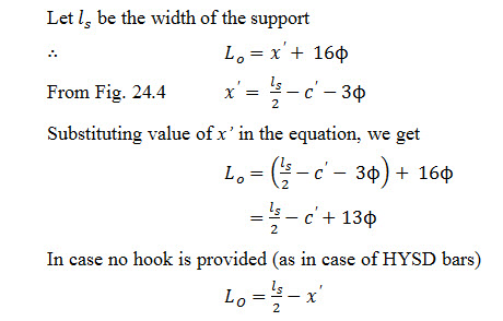
Let c’ = side cover to the reinforcing bar.
x’ = length of the bar from centre line of the support to the beginning of the hook.
L0 = sum of anchorage beyond the centre of support and the equivalent anchorage value.
In Fig. 24.4 the blackened portion of the bar shows the standard hook having an anchorage value of 16. In case of standard hook of mild steel reinforcement the anchorage value of the length of the bar between the beginning of the hook and the outer face of the hook can be taken as 3.
(c) Negative moment reinforcement. At least one-third of the total reinforcement provided for negative moment at the support shall extend beyond the point of inflection for a distance not less than the effective depth of the member or 12 or one sixteenth of the clear span whichever is greater.
24.10 LAP SPLICE
When it is necessary to provide laps in reinforcing bars the length of lap shall not be less than the following values. The splices should be staggered and as far as possible provided away from sections of maximum stress.
24.10.1 Lap Length for Bars in Flexural Tension
The minimum lap length for bars in flexural tension including anchorage value of hooks shall be greater of the following
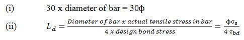
The straight length of lap shall, however, not be less than 15Ø or 20 cm. If Ø be the diameter of plain m.s.round bar; be the actual tensile stress in bar; M 15 be the grade of concrete used (for which design bond stress=0.6 N/mm2), the lap length of bar for case (ii) above will be
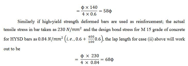
24.10.2 Lap Length for Bars in Direct Tension
The minimum lap length for bars in direct tension including anchorage value of hooks shall be greater of the following:
(i) 30Ø
(ii) 2Ld
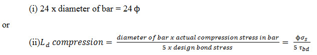
24.10.3 Lap Length for Bars in Compresion
The minimum lap length for bars in compression shall be greater of the following
24.10.4 Splicing Bars of Different Diameter
When bars of two different diameter are to be spliced, the lap length shall be calculated on the basis of the smaller diameter bar since the force to be transmitted at the slice is governed by the thinner bar.
24.11 ANCHORAGE VALUE OF BEND
If a bar in tension has its end bent to a hooked shape, the calculated development length of the bar shall be reduced by a length equal to the anchorage value of the type of hook provided. The anchorage value of standard semi-circular hook, 45˚ bend and standard L-hook is taken as 16Ø , 12Ø and 8Ø respectively of the hooked bar.
For a bar in compression, no hooks need be provided as they deprive the bar of its proper axial end bearing and also tend to cause outward buckling of the bar.
Normally, deformed bars are not provided with end hooks.
24.12 BENDING MOMENT CO-EFFICIENTS FOR BEAMS AND SLABS
The following cases are considered:
(a) Simply supported members
(b) Members continuous over two spans
(c) Members continuous over three or more spans.
24.12. 1 For Simply Supported Members
In case of simply supported beams and slabs, resting on two supports or having only one span and loaded with uniformly distributed load
Max +ve B.M. is given by
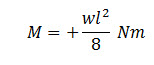
Where
w = {Sum of total dead load + imposed load (fixed) + imposed load (not fixed)} in Newton per metre.
and l = effective span of the member in metres.
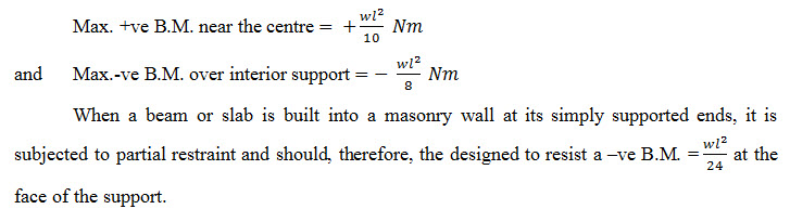
24.12.2 For Members Continuous Over Two Equal or Approximately Equal Spans
In case of beams and slabs continuous for two equal or approximately equal spans (the spans are considered approximately equal when they do not differ in length by more than 15% of the longest span) and loaded with uniformly distributed load.
24.12.3 For Members Continuous Over three of more Approximately Equal Spans
In case of beams and slabs continuous over three or more approximately equal spans (the spans are considered approximately equal when they do not differ in length by more than 15% of the longest span) and loaded with uniformly distributed load, the bending moments at the mid-span and support can be worked out by use of the following formulae as given in IS: 456-1978.
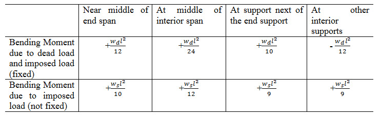
where
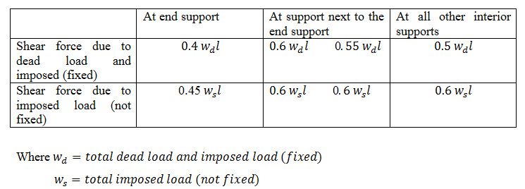
wd= Total dead load and imposed load (fixed)
ws = Total imposed load (not fixed)
l = effective span
24.13 SHEAR FORCE CO-EFFICIENTS FOR BEAMS AND SLABS
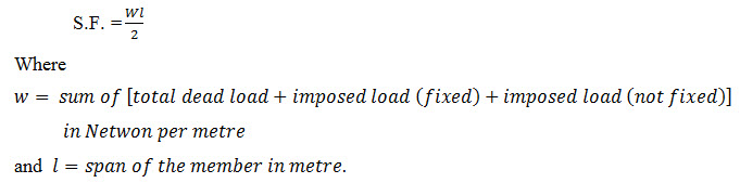
24.13.1 For Beams and Slabs Simply Supported over Span or Continuous for Two Spans
In case of beams and slab simply supported over one span or continuous for two spans and loaded with uniformly distributed load, the shear force is given by
24.13.2 For Beams and Slabs Continuous over three or more Spans
In case of beams and slabs continuous over three or more spans which do not differ by more than 15% and loaded with uniformly distributed load, the shear force at different supports can be worked out by use of following formulae as given in IS: 456-1978.
24.14 MODULAR RATIO
The value of modular ratio m for any desired grade of concrete can be obtained by the empirical formula
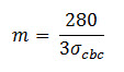
Where σcbc is permissible compressive stress due to bending in concrete in N/mm2 .
24.15 UNIT WEIGHT OF PLAIN CONCRETE AND R.C.C.
Based on recommendation in revised code, the unit weight of plain cement concrete and reinforced cement concrete shall be taken as 24000 N/m3 and 25000 N/m3 respectively.
24.16 GENERAL
1. The check for bond stress specified in the earlier code is now replaced by the concept of development length. In order to ensure development of required stresses in reinforcing bar at any section, it is necessary to extend the bar on either side of the section by appropriate development of length.
2. It is desirable to use one type of reinforcing steel bar (either plain bars or deformed bars) in the design or detailing of a member to avoid chances of error while executing the work. The secondary reinforcement like lies and stirrups can however, invariably be of mild steel even when the main reinforcement consists of HYSD bars.
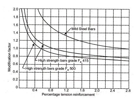
Fig. 24.1 Modification factor for tension reinforcement
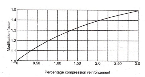
Fig. 24.2 Modification factor for compression reinforcement
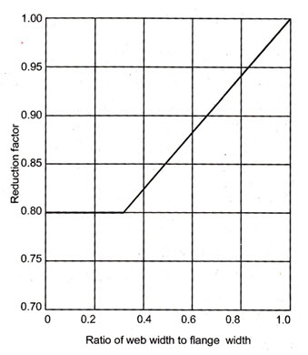
Fig. 24.3 Reduction factor for ratios of span to effective depth for flanged beams
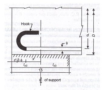
Fig. 24.4 Curtailment of tension reinforcement in flexural members
Last modified: Friday, 28 March 2014, 8:27 AM