Site pages
Current course
Participants
General
MODULE 1.
MODULE 2.
MODULE 3.
MODULE 4.
MODULE 5.
MODULE 6.
MODULE 7.
MODULE 8.
MODULE 9.
MODULE 10.
MODULE 11.
MODULE 12.
LESSON 22. Shear Stress in Beams
22.1 SHEAR STRESSES INDUCED IN HOMOGENEOUS BEAMS
If a beam of homogeneous material is loaded with a concentrated load say W, the shear force at any section of the beam on account of the load would be equal to . If equal resistance to the shear force could be offered throughout the depth of the beam, the shear stress at the section of the beam
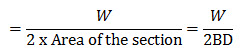
would have been and hence the shear force diagram would have been a rectangle indicating uniform shear resistance of the beam from top face to the bottom face.
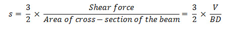
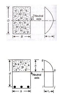
Actually, the shear stress in a homogenous beam is zero at the top and bottom face of the beam and increases to its maximum value at the neutral axis of the beam i.e., at . Hence, the stress diagram is parabolic as shown in the Fig. 22.1. It can be proved by simple mechanics that the maximum shear stress in the beam,
Where V= maximum shear force in the beam.
22.2 SHEAR STRESS INDUCED IN R.C. BEAMS
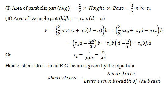
In case of reinforced concrete beam, the concrete below the neutral axis in neglected and S.F. is assumed to be resisted by the bond between the steel and the concrete. Hence, the shear stress in a R.C. beam increase from zero at the top face of the beam to its maximum value at the neutral axis and from neutral axis down to the C.G. of the reinforcing bars, it remains uniform as shown in Fig. 22.2.
If V be the total shear force in the beam then, from stress diagram.
V = Area of stress diagram x Breadth of the beam.
Area of the stress diagram consists of two parts.
22.3 NOMINAL SHEAR STRESS
In IS: 456-1978 the equation for shear stress given above has been simplified by dropping the lever arm factor and by changing the term shear stress by the term nominal shear stress. This simplification is reasonable since the nom.inal shear stress represents merely a measure of the average intensity of stress in the beam.
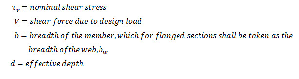
The formula for calculating nominal shear stress in beams or slab of uniform depth specified in the code is ![]()
Where
22.3.1 Nominal Shear Stress in Case Beams of Varying Depth
Beams of uniform width and varying depths are commonly used in practice. Cantilever beams continuous beam with haunches at support, footings etc. fall under this category. In case of beams of varying depth the nominal shear stress is calculated by the modified equation given below.
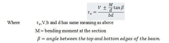
The negative sign in the formula applies when the bending moment M increases numerically in the same direction as the effective depth d increases and the positive sign when the moment decreases numerically in this direction.
22.4 EFFECT OF SHEAR IN R.C. BEAMS
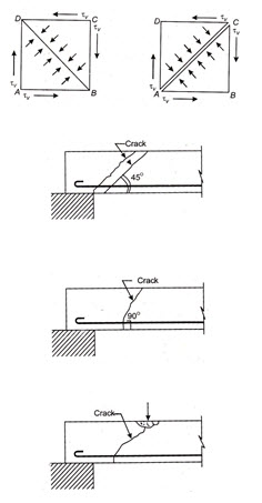
The effect of shear in R.C. beams is to create principal tensile and compression stresses equal in magnitude to the shear stress as obtained by normal shear stress equation given above but acting at 45˚ to the horizontal.
The effect of shear on a block ABCD is shown in Fig. 22.3. It is noted that when the block is subjected to shear stress of intensity, compressive stresses are developed along the diagonal plane BD and tensile stresses are developed along the diagonal plane AC. The intensity of the diagonal compressive or tensile stress being each equal to . Thus if the block is weak in compression, it will fail by the crushing of a material of the block on account of the diagonal compressive stress along diagonal plane BD. On the other hand, if the material of the block is weak in tension, it will have a tendency to split up into two parts along the diagonal plane AC.
22.5 SHEAR FAILURE OF BEAMS WITHOUT SHEAR REINFORCEMENT
As an outcome of rigorous experimental test it has been observed that beams without shear reinforcement can fail in the following ways.
(a) Diagonal tension failure: In this type of failure diagonal cracks appear in the beams (near support) which are inclined nearly at 45˚ to the horizontal as shown in Fig. 22.4. This situation arises when magnitude of shear force is large in relation to bending moment.
(b) Flexural shear failure. In this case the cracks appear normally at 90˚ to the horizontal as shown in Fig. 22.5. This type of failure occurs when bending moment is comparatively large in relation to the shear force.
(c) Diagonal compression failure. This type of failure takes place by crushing of concrete in the compression zone near the load as the diagonal crack formed independently penetrates in that zone as shown in Fig. 22.6.
Shear reinforcement essentially provided to prevent formation of crack and failure of the beam due to shear. To guard against diagonal compression failure highlighted in team (c) above, the code has fixed the upper limit for maximum allowable shear stress in a member.
22.6 SHEAR RESISTANCE OF CONCRETE WITHOUT SHEAR REINFORCEMENT
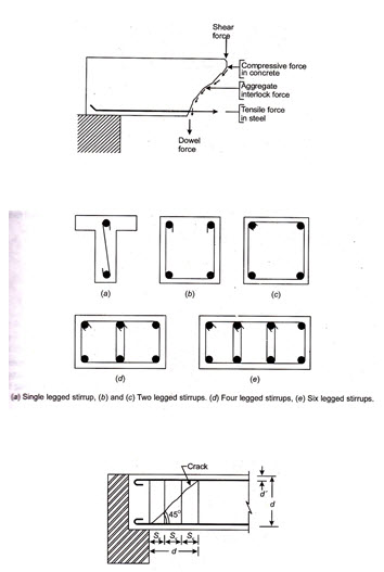
As a result of extensive studies it has been established that concrete in beam without shear reinforcement is capable of resisting certain amount of shear force. This shear strength or shear resistance of concrete is due to many factors (refer Fig. 22.7) the most important of which are:
(a) Shear force resisted by uncracked compression zone of concrete.
(b) Shear force resisted by vertical component of the force due to aggregate interlock.
(c) Shear force across longitudinal tensile reinforcement in beam (also known as dowel force).
IS: 456-1978 has specified values of permissible shear stress in concrete ( which account for the cumulative effect of all the above factors for working out the shear resistance of concrete. The value of ( for different grades of concrete and different percentage of longitudinal tensile reinforcement as given in the code are reproduced in Table 22.1
Table 22.1 Permissible shear stress in concrete
|
|
Permissible shear stress in concrete( in N/mm2 in different grades of concrete |
|||||
|
M15 |
M 20 |
M25 |
M30 |
M35 |
M40 |
|
|
0.25 |
0.22 |
0.22 |
0.23 |
0.23 |
0.23 |
0.23 |
|
0.50 |
0.29 |
0.30 |
0.31 |
0.31 |
0.31 |
0.32 |
|
0.75 |
0.34 |
0.35 |
0.36 |
0.37 |
0.37 |
0.38 |
|
1.00 |
0.37 |
0.39 |
0.40 |
0.41 |
0.42 |
0.42 |
|
1.25 |
0.40 |
0.42 |
0.44 |
0.45 |
0.45 |
0.46 |
|
1.50 |
0.42 |
0.45 |
0.46 |
0.48 |
0.49 |
0.49 |
|
1.75 |
0.44 |
0.47 |
0.49 |
0.50 |
0.52 |
0.52 |
|
2.00 |
0.44 |
0.49 |
0.51 |
0.53 |
0.54 |
0.55 |
|
2.25 |
0.44 |
0.51 |
0.53 |
0.55 |
0.56 |
0.57 |
|
2.50 |
0.44 |
0.51 |
0.55 |
0.57 |
0.58 |
0.60 |
|
2.75 |
0.44 |
0.51 |
0.56 |
0.58 |
0.60 |
0.62 |
|
3.00 and above |
0.44 |
0.51 |
0.57 |
0.60 |
0.62 |
0.63 |
Note : As is that area of longitudinal tension reinforcement which continues at least one effective depth beyond the section being considered except at supports where the full area of tension reinforcement may be used.
The shear resistance of concrete (Vc) in a beam is worked out by multiplying value of obtained from Table 22.1 with cross-sectional area of the beam i.e., shear force resisted by concrete ![]()
22.7 DESIGN SHEAR STRENGTH OF CONCRETE
(i) Permissible shear stress in concrete without shear reinforcement: The permissible shear stress in concrete in beams without shear reinforcement shall be as given Table 22.1
For solid slabs the permissible shear stress in concrete, shall be where K has the value given in Table 22.2
Table 5.2 K value
|
Overall depth of slab in (mm) |
300 or more |
275 |
250 |
225 |
200 |
175 |
150 or less |
|
K |
1.00 |
1.05 |
1.10 |
1.15 |
1.20 |
1.25 |
1.30 |
Note : The above do not apply to flat slabs.
(ii) Permissible shear stress in concrete with shear reinforcement. When shear reinforcement is provided the nominal shear stress ( in beams shall not exceed. Given in Table 22.2.
Table 5.3 Maximum shear stress in beams
|
Grade of concrete |
M 15 |
M 20 |
M 25 |
M 10 |
M 35 |
M 35 |
M 40 |
|
1.6 |
1.8 |
1.9 |
2.2 |
2.3 |
2.5 |
2.5 |
Maximum shear stress for slabs: For slabs shall not exceed half the value of given in Table 22.2.
22.8 MINIMUM SHEAR REINFORCMENT
It has now been established that in beam without shear reinforcement sudden diagonal tension failure occur without warning. This makes such a member unsafe. It is observed that provision of certain minimum amount of shear reinforcement (even if the shear force developed at the section is less than shear resistance of concrete) has a distinct advantage. Such reinforcement besides resisting part of shear by itself also improves the capacity of concrete compression zone and the longitudinal tensile reinforcement to resist shear. The minimum shear reinforcement specified in the code also caters for any sudden transfer of tensile stress from the web concrete to the shear reinforcement.
As per IS: 456-1978 when the value of the nominal shear ( as calculated from equation works out to be less than the permissible shear stress in concrete (, minimum shear reinforcement in the form of stirrups, shall be provided in accordance with the relation
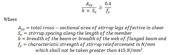
The term characteristic strength is defined as the strength of material below which not more than 5 per cent of the test results are expected to fall. For mild steel reinforcement is taken = 250 N/mm2 and for High Yield Strength Deformed bars (HYSD bars) is taken = 415 N/mm2.
The above provision need not be applied to members of minor structural importance such as lintels or when the maximum shear stress calculated ( is less than half the permissible shear stress in concrete (.
The above equation can be re-arranged as under to obtain an expression giving maximum c/c spacing of stirrups required for minimum shear reinforcement 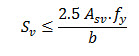
22.9 MAXIMUM SPACING OF SHEAR REINFORCEMENT
As per IS: 456-1978 the maximum spacing of shear reinforcement measured along the axis of the member shall be as under
(i) For vertical stirrups 0.75d or 450mm whichever is less
(ii) For inclined stirrups at 45˚ d or 450mm whichever is less
Where d is the effective depth of the member.
22.10 DESIGN OF SHEAR REINFORCEMENT
When the shear force-V (or shear stress ) at a section exceeds the shear resistance of concrete (or permissible shear stress in concrete-) shear reinforcement have to be provided to prevent formation of cracks or failure of the member. The method of designing shear reinforcement based on the truss analogy is accepted by the code. In this analogy it is assumed that concrete and the shear reinforcement form a lattice-grider truss wherein tension is carried by the longitudinal bars and the shear reinforcement and the concrete carries the thrust in the compression zone and the diagonal thrust across the web.
If be the shear force to be carried by the shear reinforcement, the shear capacity of a section can be written as ![]()
In this expression the values of V (i.e., the shear force due to design loads) and Vc (i.e., shear resistance of concrete = ) are known and as such in normal practice the design procedure will involve the determination of shear reinforcement for shear force = Shear reinforcement can be provided in any of the following forms:
(i) In the form of vertical bars known as stirrups.
(ii) In the form of bent up bars along with the stirrups.
(iii) In the form of inclined stirrups.
The design of different forms of shear reinforcement is described in the following articles.
22.10.1 Design of Vertical Stirrups
Vertical stirrups may consist of 5mm to 12mm diameter bars bent around the tension reinforcement and their free ends taken into the compression zone of the beam. In the compression zone the stirrups are anchored to the longitudinal bars (known as anchor bars) so that the vertical legs may resist tension without slippage. In case of doubly reinforced beams the stirrups are taken around the compression reinforcement and suitably anchored. Depending upon the magnitude of shear force ( to be resisted, the vertical stirrups may be one legged, two legged, four legged, six legged and so on. The various form of stirrups are shown in Fig. 22.8.
To derive an expression for shear force resisted by vertical stirrups.
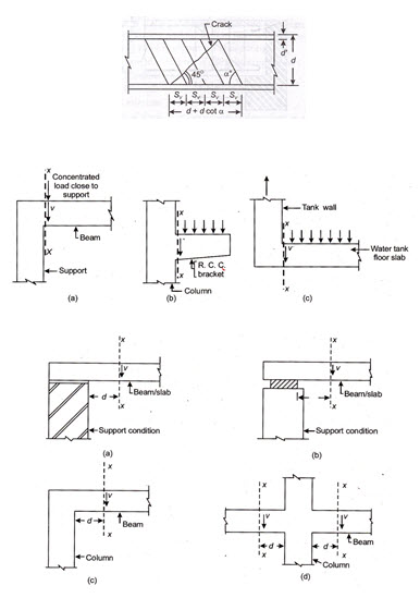
Let us assume that concrete has failed in diagonal tension on account of shear force. Let the diagonal crack be inclined at 45˚ to the axis of the beam and extend to the full depth of the beam. The horizontal distance up to which the crack extends will therefore be equal to the effective depth (d) of the beam – cover (d’) to the anchor bars.
Since d’ is very small as compared to d we may consider the distance of horizontal extension of crack as d.
The above formula is adopted for the design of vertical stirrups as shear reinforcement. In the formula, the values of , and d are known. We assume suitable diameter and number of legs for the stirrups ( and work out the c/c spacing of the stirrups by re-writing the above formula as under 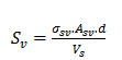
It should, however, be ensured that:
(1) The area of shear reinforcement ( provided is not less than the area of minimum shear reinforcement specified by the code (Ref. Art 22.8).
(2) The centre to centre spacing () does not exceed the maximum limits prescribed in the code. (Ref. Art. 22.9).
22.10.2 Design of Inclined Bars or Inclined Stirrups as Sheer Reinforcement
In a beam some longitudinal bars can be bent up near support where they are no longer needed to resist bending moment. The bars can be bent up at uniform spacing at different cross-
section along the length of the beam or all the bars (which are no longer needed for resisting B.M.) can be kept up at the same cross-section.
The bars thus bent up are helpful in resisting shear. In order to be fully effective in shear the bent up bars are continued beyond the neutral axis in the compression zone for a distance equal to the development length. (For details regarding development length refer Lesson 23).
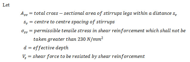
The expression for shear force resisted by the inclined bars can be derived by considering the truss analogy. Instead of bending up bars some designers prefer to use inclined stirrups. The case of inclined stirrups or bent up bars is identical and as such the following formula will apply to both bent up bars as well as inclined stirrups.
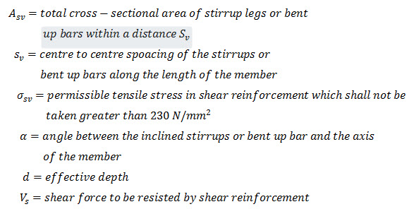
Let
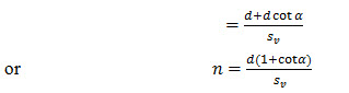
Case I. For inclined stirrups or a series of bars bent up at different cross-section.
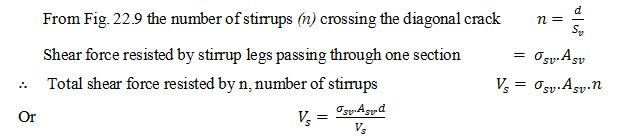
From the Fig.(22.10) it can be seen that the number of inclined bars or stirrups (n) crossing the diagonal crack
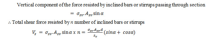
Case II. For single bar or single group of parallel bars, all bent up at the same cross-section.
As already explained in derivation in Case I above ![]()
IS: 456-1978 does not permit the shear reinforcement to be entirely provided in the form of bent up bars since there is insufficient evidence to show that such reinforcement is satisfactory. As per code where bent up bars are provided as shear reinforcement their contribution towards shear resistance shall not be taken more than half that of the total shear reinforcement.
In other words the bent up bars can be used only in combination with stirrups, where the stirrups must make up 50% of the total shear reinforcement. In situations where more than one type of shear reinforcement is used to reinforce the same portion in of the beam, the total shear resistance shall be computed as the sum of the resistance for various types separately. The area of the stirrups shall not be less than the minimum specified in Art. 22.8.
22.11 CRITICAL SECTION FOR SHEAR
As per IS: 456-1978 the shear computed at the face of support shall be used in the design of the member at that section except when the reaction in the direction of the applied shear introduces compression into the end region of the member, sections located at a distance less than d from the face of the support may be designed for the same shear as that computed at distance d.
Fig. 22.11 shows examples of cases where the support reaction does not include compression in the end region. In such situation a diagonal shear crack is likely to start at the face of support. Hence the critical section for shear (section X – X) is taken at the face of the support.
In all cases shown Fig. 22.12 the reaction from the beam/slab introduces compression in the end region which has the advantage of displacing the diagonal shear crack away from the face of the support. Hence the code allows the support section to be designed for shear computed at a distance d away from the support. Thus the critical section for shear may in such case be treated to be located at a distance d from the face of the support.
It is however, proposed to consider critical section for shear at the face of the support in the above referred cases in Fig. 22.12 to simplify design. The following examples have been solved accordingly.
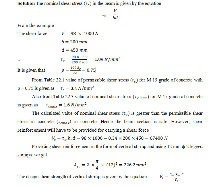
Example 22.1 A reinforced concrete beam 200 mm wide and 450 mm deep to the centre of tensile reinforcement is subjected to shear force of 98 kN at the supports. The area of the tensile steel available at the supports is 0.75 per cent. Design suitable shear reinforcement for the beam. Also calculate the minimum shear reinforcement for the beam. Adopt the following data

Maximum spacing for shear reinforcement. As per rules the maximum spacing of the stirrups should not exceed 0.75 d or 450 mm whichever is less. In this case
0.75 d = 0.75 x 450 = 337.5 mm = 335 mm (say)
The maximum spacing of stirrups as permissible under rule is less than obtained from requirement of minimum shear reinforcement .
Hence provide 10 mm 2 legged stirrups @ 335 mm c/c.
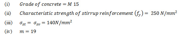
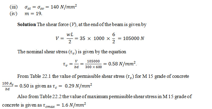
Example 5.2 A simply supported reinforced concrete beam, 300 mm wide and having an effective depth of 600 mm carries a uniformly distributed load of 35 kN/m (inclusive of its own weight) over a clear span of 6m. Design suitable shear reinforcement for the beam assuming that 0.5% tensile reinforcement is available throughout its length. The following data being given:
(i) Grade of concrete = M 15
(ii) Characteristic strength of stirrup reinforcement ( = 250 N/mm2
The calculated value of nominal shear stress is less than . Hence the beam section is O.K.
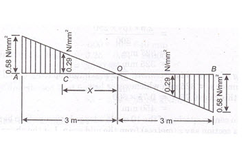
However, since the value of nominal shear stress is more than the permissible shear stress , shear reinforcement will have to be designed for section near support. The shear stress diagram for the beam is shown in the Fig. 22.13.
To calculated distance x from the centre of the beam, where permissible shear stress ( less than(), shear reinforcement will have to be designed for section near support.
The shear stress diagram for the beam is shown in the Fig. 5.13.
To calculate distance x from the centre of the beam, where permissible shear stress is developed. From Fig. 22.13, we have
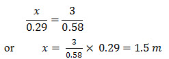
Hence the designed shear reinforcement is required in length AC or BD = 3 – 1.5 = 1.5 m from either end. In the remaining length CD, nominal shear reinforcement is to be provided to meet the requirement of minimum shear reinforcement in the beam.
Design of shear reinforcement. Magnitude of shear force (Vs) for which shear reinforcement is to be designed is given by
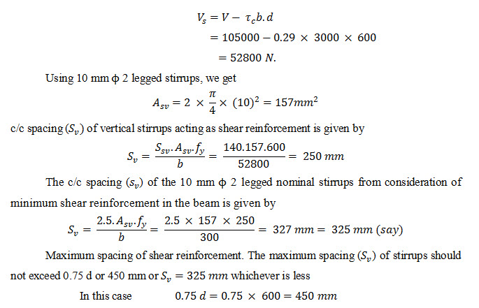
Hence the centre to centre spacing of the 10 mm 2 legged stirrups is to be varied from 250 mm at ends to 325 mm at a section say z (meters) from the mid span. Let the shear force at that section be = .
From S.F diagram
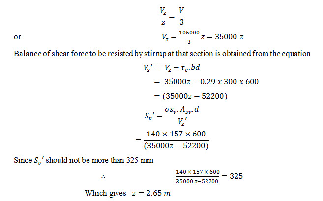
Hence vary the c/c spacing of 10 mm 2 legged stirrups from 250 mm at end to 325 mm c/c at 2.65m from mid span. For the remaining length provide the stirrups at spacing of 325 mm c/c.
Last modified: Saturday, 5 October 2013, 8:51 AM