Site pages
Current course
Participants
General
Module 1 - Water availability and demand and Natio...
Module 2 - Irrigation projects and schemes of India
Module 3 - Concepts and definitions
Module 4 - Command Area Development and Water Mana...
Module 5 - On-Farm-Development works
Module 6 - Water Productivity
Module 7 - Tank & Tube well irrigation
Module 8 - Remote Sensing and GIS in Water Management
Module 9 - Participatory Irrigation Management
Module 10 - Water Pricing & Auditing
LESSON 17. Chak Water Delivery System – Control Structures
Introduction
The structures on field channel include measuring device, drop/falls, Diversion Boxes, Turnouts, Road crossing, etc. The design, construction and other aspects of these structures except flow measuring devices are discussed below. The details of flow measuring devices are given in Lesson 19.
17.1 Drop or Falls:
The important structure on the field channel is a drop, or a fall. The field channel gradient should follow the natural slope of the land, to have minimum number of drop structures. However, many a times the natural slope of the lands is steeper than the allowable steepest gradients in field channels. In such cases, the gradients have to be flattened by providing small vertical drops on channels. In the vertical drop, water falls through a certain height and potential energy is converted into kinetic energy, thus resulting in a high velocity downstream. This high velocity is likely to cause erosion and damage to the channel downstream. It is therefore necessary to dissipate the extra energy and ensure that the velocity at the end of structure is reduced to non-erodible velocity. Various types of fall structures, developed mostly on model studies, are available. Since these structures are usually small structures but large in numbers, individual design is not practically feasible. The type designs are, therefore, used.
The drops in the field channels are basically similar to those on the distributory or main canal and their functioning is the same. The only difference is that these structures are small in size but large in numbers and hence their construction has to be simpler. The drop basically consists of three components:
− Cut-off walls, long and deep enough to prevent leakage and outflanking of channel flow
− an opening in the channel, and
− a stilling basin with some sort of end sill.
All the type designs in use are basically combinations of these three, with variations in dimensions of each component. The conventional type designs are described below:
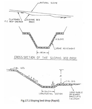
17.1.1 Sloping Bed Drop (rapid):
The sloping bed drop is one of the low cost designs. It can be used only where ood hard strata is available, it can be used upto 1 m drop height. Moreover, the channel has to be in cutting. The sketch in Figure-5.4 explains the details. This structure can be constructed with RCC half round 450 mm diameter pipes laid on slopping ground with energy dissipation arrangement at the end.
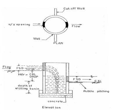
17.1.2 Vertical Well Type Drop:
Another low cost structure is the vertical well type drop. It consists of a vertical well with a concrete bottom and two openings. One opening in the well at a higher level is on the upstream side and allows the water in the channel into the well. The second opening is at the downstream and allows water into the downstream channel from the well. The bottom of the two openings are at the bed levels of the upstream channel and the downstream channel respectively. The bed level of the well is at a lower level than the downstream opening. The portion of the well between the sill level of the downstream opening and the bed level of the well acts as a stilling basin for dissipation of the energy. A cut-off wall is also provided to arrest the leakage or bypassing (out-flanking) of the water. A schematic arrangement is shown in Figure-17.2. The length of cut-off wall should be adequate to eliminate out flanking.
Wells have been tried with steel barrels, R.C.C. spun pipes and masonry, it is experienced that the R.C.C. spun pipes serve well. They can be procured very early in bulk quantity and erected on site. They are cheaper than masonry and equally sturdy. However, if the selected diameter of the well is different from standard pipe dimensions, masonry well can be used. RCC hume pipe of 600 mm to 800 mm diameter of required depth attached with horizontal RCC hume pipe of 300 mm diameter at u/s and d/s end embedded in UCR masonry head wall can be used as a fall. This type of pipe fall can be used as field road crossing also. The opening should be equal to the width of the channel. The height of the opening should be about 1.5 times the depth of water in the channel. The diameter of the well has to be carefully selected, so that energy dissipation is satisfactory.
 The diameter can be selected from,
![]()
where , V = the volume of the stilling basin in m3
Hdr = Height of drop in m.
(i.e. the difference between the sill level of upstream and downstream)
Q = discharge of the channel in litre per second.
Once the volume of the stilling basin is determined, the height of the stilling basin and the diameter of the well can be computed by selecting one parameter and calculating the other. The height of the stilling basin should not be less than half the height of the drop. The above formula gives the minimum value of the volume but a slightly greater volume is always welcome.
17.1.3 Vertical Rectangular Drop:
A commonly used type of drop is the vertical rectangular drop. At the inlet there is a vertical wall over which water falls from a higher level to a lower level in a vertical rectangular well. At the downstream, the wall of the well is dwarf. The water forms a pool in the stilling basin of the well and flows over the dwarf wall in the downstream channel. The bed level of downstream channel coincides with the top of the dwarf wall. The general arrangement is illustrated in Figures -17.3 to 5.
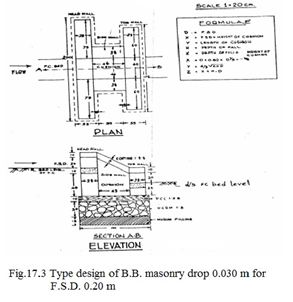
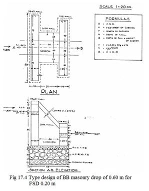
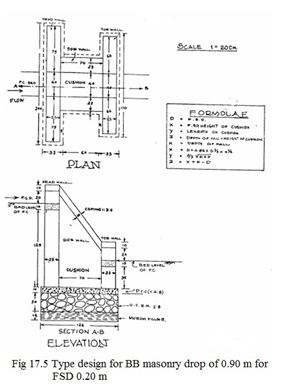
The walls are about 0.23 m thick in B.B. masonry and 0.4 m. thick in U.C.R. masonry with 0.10 m concrete coping. The length, breadth and depth of the rectangular basin is to be designed. The commonly used formulae as per F.A.O.Paper No. 26/2 are:

where
V = the volume of the stilling basin in m3
Hdr = Height of drop in m.
Q = discharge of the channel in litre per second.
Length of basin, Lbs = 1.5 Hdr meter
Width of basin = [V/{Lbs(Y2+dbs)}] meters
The depth of the basin (dbs) is from - 0.1 to 0.3 m and other dimensions are worked out by trial and error. Presently, the width of the basin is kept the same as the bed width of the upstream channel for ease of construction and design. As per norms, the basin depth and length are worked out by,
dbs = 0.82 x Y21/3 x Hdr1/2
Lbs = 1.33 x Y21/2(Hdr + dbs) ½
Where Y2 = upstream full supply depth (F.S.D.)
Three type designs, for drops of 0.3 m. 0.6 m, 0.9 m, B.B. masonry are given in Figure 17.3, 17.4 and 17.5 respectively. These illustrate only the general arrangements. The dimensions have to be modified to suit the specific conditions.
In order to keep overall expenditure of OFD works within reasonable limits (or cost norms laid down by Government) the number of drops on Field Channel should be minimum. However, following physical norms are enumerated as guidelines and these indicate ceiling limits.
|
S. No. |
Ground slope |
No. of drops per ha of chak |
|
1. |
Less than 1% |
NIL |
|
2. |
1% - 2% |
½ |
|
3. |
2% - 3% |
1 |
|
4. |
Above 3% |
1½ |
17.2 Diversion Box (DB):
The diversion or division box is provided in the field channel where it branches off in two or three directions. The purpose of the box is to divert the flow into any one branch. The structure consists of a rectangular box with openings in the vertical sidewalls, and wing walls extending in the directions of the field channel and branches. If the field channel branches into two directions, a two way divisions box is provided while if it branches into 3, three - way division boxes are provided. These are constructed in situ, in brick or in stone masonry, depending upon the availability of the material locally. Precast concrete division boxes are also readily available. They can be transported in places to the site and assembled there. A sketch of precast two-way D.B. and rubble masonry three-way division boxes are given in Figure-17.6 & 17.7. The height of D.B. be restricted upto top of F.C. bank to reduce the cost.
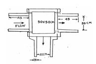
Fig:17.6 Precast diversion box (Two way)
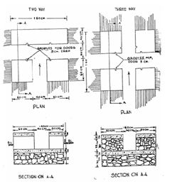
Fig:17.7 Diversion box in R.R. masonry
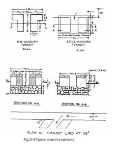
17.3 Turnout:
Turnout is a structure on field channel from where water is diverted from field channel to the field. It is either a clay or cement spun pipe embedded in masonry. The location of the turnout should be such that it should be able to cater to the maximum area in the individual holding. The location should invariably be fixed in consultation with the farmer, so that he will not be tempted to open the field channel at some other location to get water. If two turnouts are located at one point, normally a diversion box is cheaper and serves the purpose equally well. A type drawing of the turnout is presented in Figure-17.8 & 17.9. In order to have smooth entry of water into turnout, it may be laid at 45° if possible (Figure 5.13). If the turnouts are more in number, dry rubble turnouts may be used to reduce the cost. Pipe turnout can also be used.
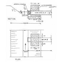
Fig.17.8 Pipe turn out
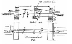
17.4 Crossings:
The channel normally runs on a local ridge or the field boundaries. A case of field channel, crossing the natural drain, is therefore, almost an exception. The field channel has, however, to cross the cart tracks in the field. In this case, the bed gradient and the alignment of the field channel need not be changed. A simple arrangement is to provide a spun pipe of 300-mm dia (NP-3) as waterway to the field channel, fixed in two masonry headwalls. The width of the crossing i.e. the distance between the head walls depends on the width of the road. The foundation of the head walls should rest on hard strata like hard murum, or else the foundation treatment for soft soils may be given. A minimum cover of 30 to 45 cm of hard murum over the Hume pipe is necessary. Earth filling should be provided in the space surrounding the Hume pipe and between the head walls. A sketch of the arrangement is given in Figure-5.14. If there is a scope for sufficient cushioning, pipes of diameter more than 300 mm may be used.
17.5 Farm Roads:
One of the difficulties faced by the cultivators is to take their produce out of the chak and to carry the inputs to the fields. The old cart track-cum-natural drains are not useful to them when irrigation starts. As yet, except in few states where consolidation of land holdings is practiced, no farm roads are constructed or planned. In a well-laid out system every farm should have an approach to the link road, leading further to the villages or markets. Therefore, it would be advisable, during the design of O.F.D. Works, to at least plan the farm roads and decide the crossings, so that the planning is comprehensive. As a rough estimate, the length of the farm roads per ha is 30 m and the number of crossing per ha. is 0.4.
Last modified: Tuesday, 18 February 2014, 8:18 AM