Site pages
Current course
Participants
General
Module 1 - Water availability and demand and Natio...
Module 2 - Irrigation projects and schemes of India
Module 3 - Concepts and definitions
Module 4 - Command Area Development and Water Mana...
Module 5 - On-Farm-Development works
Module 6 - Water Productivity
Module 7 - Tank & Tube well irrigation
Module 8 - Remote Sensing and GIS in Water Management
Module 9 - Participatory Irrigation Management
Module 10 - Water Pricing & Auditing
LESSON 19. Flow Measuring Devices For Field Channels
Introduction
In any irrigation systems, there should be a commitment to deliver a specific amount of water in a specific time to the irrigators. This means flow volume is assured. Not only the management staff should be able to measure the stream flow rate, but also the irrigator should be able to verify that the promised stream flow (30 lps. in Maharashtra) is being delivered to him. This facility can create a confidence in the minds of farmer towards the system. Reasonable accurate water measurement is also necessary to ensure proper delivery schedules, to determine the amount of water delivered and to estimate or detect the conveyance losses. It also helps in field trials and evaluation of actual irrigation efficiencies, etc.
A measuring device is, therefore, fixed in the initial reach of the field channel system of every chak. The device should be located on a 10 to 20 m straight reach. If a drop is available in this portion, it can be combined with the measuring device.
If Self-Regulated (SR) outlet is used to deliver the water, separate measuring devices may not be necessary as this outlet delivers almost constant discharge (upto 10% variation) under given modular range.
A good measuring device indicates the discharge with preferably single guage reading and it should be reasonably accurate within the given range of discharge. The device should not be unduly sensitive to changes in the type of flow and levels of upstream and downstream, particularly the approach velocity in the upstream and some silting or erosion on the downstream.
For small discharges the above conditions are satisfied by the following measuring devices:
a) V-notch
b) Cut-throat flume
c) Replogle flume.
If drop/fall is available, V-Notch is suitable device. If not, Replogle Flume may be selected, as it is easy to construct, low in cost. The Cutthroat flume if available in pre-fabricated form can also be used provided setting is properly worked out and executed.
19.1 V-Notch:
Generally 90° V-notch is quite often used to measure small discharge (say upto 30 to 40 lps) in field channels where falls are available. The downstream water level must be at least 15 cm below the vertex or crest of the notch. This implies an available drop of about 45 to 50 cm. Advantages of V-notch are its low cost and ease in construction. Figure-19.1 shows the fixing of 90° V-notch in field channel.
19.1.1 Discharge Formula:
The Kindsvater-Shen formula for thin plate V-notch is:
![]()
Here α is the angle of notch. For a 90° notch the formula becomes,
![]()
In which
Q = discharge in cumec
Ce = Co-efficient of discharge, and
H = effective head, m = h + kh
(For a 90° notch, kh = 0.85 mm, or 0.085 cm)
g = 9.81 m/s2
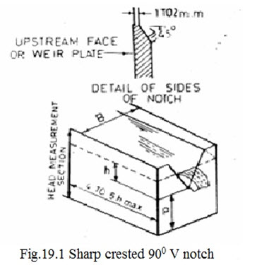
For a 90° notch, the co-efficient of discharge Ce is a function of two variations h/ p and P/B.
In which,
P = height of the vertex of the notch above the channel bed
B = Width of the approach channel
h = head above the vertex of the notch measured at a distance 4 to 5 times hmax u/s of the notch
For a 90° V-notch, the value of co-efficient of discharge Ce varies from 0.58 to 0.61 with following limitations.
a) h/p should be limited from 0.2 to 2.
b) p/B should be limited from 0.1 to 1
c) h should not be less than 6 cm
d) p should be nearly 10 cm
e) The nappe should be fully ventilated.
In general, the approach channel should be smooth, straight and rectangular for a reach not less than 20 times hmax, when B/hmax is less than 3 and/or hmax/p is greater than 1 (which is generally the condition).
Table-19.1 gives the discharge for head h varying from 6 cm to 30.5 cm for a 90°V-notch taking Co-efficient of discharge Ce equal to nearly 0.68 (for greater accuracy, refer IS-9101 – 1979. For a flow range of 30 to 70 lps in 90°V-notch, the depth of flow should be 21.5 to 30.5 cm. “Liquid Flow Measurement in Open Channels using Thin Plate Weirs” and establish the exact value of Ce for the given condition of the setting).
Precaution must be taken to see that the weir plate is truly vertical after installation and at equal distance from channel sides. The plate should be firmly embedded either in concrete or masonry. The edges of the notch should be rounded smoothly so that small eddies are not formed near the weir. The sharp-edge is chamfered on down-stream side.
TABLE – 19.1 Discharge Table for Sharp - Crested 90º V notch
|
Head |
Discharge |
Head |
Discharge |
Head |
Discharge |
Head |
Discharge |
|
H (cm) |
(lps) |
h (cm) |
(lps) |
h (cm) |
(lps) |
h (cm) |
(lps) |
|
6.0 |
1.3 |
12.5 |
7.7 |
19.0 |
21.7 |
25.0 |
43.2 |
|
6.5 |
1.5 |
13.0 |
8.5 |
19.5 |
23.2 |
25.5 |
45.4 |
|
7.0 |
1.8 |
13.5 |
9.3 |
20.0 |
24.7 |
26.0 |
47.6 |
|
7.5 |
2.2 |
14.0 |
10.2 |
20.5 |
26.3 |
26.5 |
49.9 |
|
8.0 |
2.6 |
14.5 |
11.1 |
21.0 |
27.9 |
27.0 |
52.3 |
|
8.5 |
3.0 |
15.0 |
12.1 |
21.5 |
29.6 |
27.5 |
54.8 |
|
9.0 |
3.4 |
15.5 |
13.1 |
22.0 |
31.4 |
28.0 |
57.3 |
|
9.5 |
3.9 |
16.0 |
14.2 |
22.5 |
33.2 |
28.5 |
59.9 |
|
10.0 |
4.4 |
16.5 |
15.3 |
23.0 |
35.0 |
29.0 |
62.6 |
|
10.5 |
5.0 |
17.0 |
16.5 |
23.5 |
37.0 |
29.5 |
65.3 |
|
11.0 |
5.6 |
17.5 |
17.7 |
24.0 |
39.0 |
30.0 |
68.1 |
|
11.5 |
6.2 |
18.0 |
19.0 |
24.0 |
39.0 |
30.5 |
71.0 |
|
12.0 |
6.9 |
18.5 |
20.3 |
24.5 |
41.0 |
|
|
19.2 Cut-Throat Flume:
Cut-throat flume have been developed to over come the difficulties experienced in construction of the Parshall flumes. The shape of Parshall flume especially its bottom, presents some problems of construction in the interior places, where good workmanship is not available. In Cut-throat flume, there are only two sections, a converging inlet section and a diverging outlet section. The floor of the flume is horizontal. Since the flume has no longitudinal throat portion, it is named “Cut-throat Flume”. Advantages of the Cut-throat flume over Parshall flume are:
- Ease of construction
- Angles of convergence and divergence remain the same for all size
- The rating of intermediate sizes can be developed from the available rating equations.
- It gives nearly as accurate measurements as Parshall flume in free flow condition for smaller throat widths (5% errors).
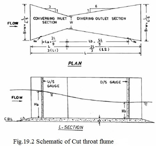
The diagrammatic sketch of the Cut-throat flume is shown in Figure-19.2. L is the total length of the flume. W is the throat width, L1 and L2 are the length of converging and diverging sections and La and Lb are the upstream and downstream gauge locations. Cut-throat flume is recognized by its throat width W and length L. In field channels 10x90 cm and 20x90 cm flumes can be used which can measure a discharge upto 54 lps and 115 lps respectively under free flow condition. In Table– 19.2 various dimensions for 10x90 cm and 20x90 cm cut-throat flumes are given. However, in order to minimize the problem of head loss and afflux it is advisable to use 20x90 cm flume. The total height of the flume from bottom may be restricted to 35 cm for economy.
Table – 6.2 Dimensions for 10x90 cm & 20x90 cm Cut-Throat Flumes
|
Throat WidthW (cm) |
L(cm) |
L1(cm) |
L2(cm) |
La(cm) |
Lb(cm) |
B(cm) |
|
10 |
90 |
30 |
60 |
20 |
50 |
30 |
|
20 |
90 |
30 |
60 |
20 |
50 |
40 |
For both 10x90 cm and 20x90 cm Cut-throat flume, free flow limit (hb/ha) is 65.3%, it is observed that cut-throat flumes are not suitable for measurements of discharges under submerged flow conditions i.e. for hb/ha more than 65%. However, in order to compute discharges under submerged flow condition, a submerged flow equation is proposed in literature. It still needs full rectification.
The discharge equation under free flow conditions is as below:
Q = C Han
Where,
Q is discharge in m³/sec.
Ha is upstream gauge reading in m.
C is discharge coefficient and n is exponent depending upon flume length.
The value of discharge coefficient C is calculated as:
C = K.W1.025
K is coefficient depending upon length of flume and W is throat width in m.
For 90cm long flume value of exponent n and coefficient K are 1.843 and 3.89 respectively.
TABLE - 6.3 Free Flow Discharge for 10x90 cm and 20x90 cm Cut-Throat Flumes
|
Upstream Head Ha (cm) |
Discharge (lps) |
Upstream Head Ha (cm) |
Discharge (lps) |
||
|
10 x 90 cm |
20 x 90 cm |
10 x 90 cm |
20 x 90 cm |
||
|
5.0 |
1.5 |
3.0 |
20.5 |
19.8 |
40.3 |
|
5.5 |
1.8 |
3.6 |
21.0 |
20.7 |
42.1 |
|
6.0 |
2.1 |
4.2 |
21.5 |
21.6 |
44.0 |
|
6.5 |
2.4 |
4.8 |
22.0 |
22.5 |
45.9 |
|
7.0 |
2.7 |
5.6 |
22.5 |
23.5 |
47.8 |
|
7.5 |
3.1 |
6.3 |
23.0 |
24.5 |
49.8 |
|
8.0 |
3.5 |
7.1 |
23.5 |
25.5 |
51.8 |
|
8.5 |
3.9 |
8.0 |
24.0 |
26.5 |
53.9 |
|
9.0 |
4.3 |
8.6 |
24.5 |
27.5 |
55.9 |
|
9.5 |
4.8 |
9.8 |
25.0 |
28.5 |
58.1 |
|
10.0 |
5.3 |
10.7 |
25.5 |
29.6 |
60.2 |
|
10.5 |
5.8 |
11.7 |
26.0 |
30.7 |
62.4 |
|
11.0 |
6.3 |
12.8 |
26.5 |
31.8 |
64.6 |
|
11.5 |
6.8 |
13.9 |
27.0 |
32.9 |
66.9 |
|
12.0 |
7.4 |
15.0 |
27.5 |
34.0 |
69.2 |
|
12.5 |
8.0 |
16.2 |
28.0 |
35.2 |
71.5 |
|
13.0 |
8.5 |
17.4 |
28.5 |
36.3 |
73.9 |
|
13.5 |
9.2 |
18.7 |
29.0 |
37.5 |
76.3 |
|
14.0 |
9.8 |
19.9 |
29.5 |
38.7 |
78.8 |
|
14.5 |
10.5 |
21.3 |
30.0 |
39.9 |
81.3 |
|
15.0 |
11.1 |
22.6 |
30.5 |
41.2 |
83.8 |
|
15.5 |
11.8 |
24.1 |
31.0 |
42.4 |
86.3 |
|
16.0 |
12.5 |
25.5 |
31.5 |
43.7 |
88.9 |
|
16.5 |
13.3 |
27.0 |
32.0 |
45.0 |
91.5 |
|
17.0 |
14.0 |
28.5 |
32.5 |
46.3 |
94.2 |
|
17.5 |
14.8 |
30.1 |
33.0 |
47.6 |
96.9 |
|
18.0 |
15.6 |
31.7 |
33.5 |
48.9 |
99.6 |
|
18.5 |
16.4 |
33.3 |
34.0 |
50.3 |
102.3 |
|
19.0 |
17.2 |
35.0 |
34.5 |
51.7 |
105.1 |
|
19.5 |
18.0 |
36.7 |
35.0 |
53.0 |
107.9 |
|
20.0 |
18.9 |
38.5 |
35.5 |
54.4 |
110.8 |
For free flow condition, discharge equation for 10x90 cm flume will become.
Q = 0.3672 Ha1.843 (M.K.S. units)
Discharge equation for 20x90 cm flume under free flow condition will be:
Q = 0.7473 Ha1.843 (M.K.S. units)
For better accuracy, upstream head Ha should be restricted to 0.4 L i.e. 36 cm. Free flow discharge tables for 10x90 cm and 20x90 cm cut-throat flume are given in Table-19.3.
Regarding gauge locations, in Cut-throat flume u/s gauge is located in converging section at a distance equal to 2L/9 measured along the axis of the flume from the throat. The d/s gauge is located in the diverging section at a distance 5L/9 from the throat.
19.2.1 Computation of Discharge for Submerged Flow Condition:
Discharge equation for submerged flow condition (Hb/Ha)100>65%) through a Cut-throat flume is
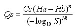
Where,
Qs = discharge under submerged flow condition in m³/s,
Cs = Submerged flow discharge coefficient,
Ha = U/s head in m
Hb = D/s head in m
n = free flow exponent depends upon flume length L,
S = Actual submergence in fraction = (Hb/Ha)
Ns = Submerged flow exponent depends upon flume length L,
Cs = Ks W1.025
Ks = Submerged flow coefficient depends upon flume length L and,
W = Throat width in m.
Submerged flow discharge equation for a given Cut-throat flume of size W x L can be developed similar to as for free flow conditions. However, it is observed experimentally that accuracy of flow measurement by using Cut-Throat flume is doubtful under submerged condition and hence not discussed. It is also advised to avoid submerged flow condition in Cut-throat flumes as far as possible. Example 1 explains how to establish submerged flow discharge equation for a given flume size W x L and then to compute discharge for observed gauge readings i.e. Ha and Hb.
Example 1:
Establish submerged flow discharge equation for 20 x 90 cm Cut-throat flume and compute discharge if measured gauge readings are as below:
Ha = 20.0 cm Hb = 16.0 cm.
Solution:
Flume size under consideration is 20 x 90 cm. For flume length 90 cm,
n = 1.843
Ns = 1.483
ks = 2.15
W = 20 cm = 0.2 m.
Cs = Ks W1.025 = 2.15 x 0.21.025 = 0.413
Submerged flow discharge equation for flume size 20 x 90 cm is:
Calculation of discharge if Ha = 20.0 cm and Hb = 16.0 cm
S = (16/20) = 0.8 (Submerged flow condition)
Put values of Ha, Hb and S in the submerged flow discharge equation, Ha = 20.0 cm = 0.2 m. Hb = 16.0 cm = 0.16 m.
0.413 (0.2 – 0.16)1.843
Qs = --------------------------- = 0.0349m³/S
(-Log100.8)1.483
Qs = 34.9 l.p.s.
19.2.2 Upper Limit for U/s Head Ha and Submergence S:
For flow measurement through a Cut-throat flume, the u/s head Ha should not exceed 0.4 x L and submergence should not be more than 95%.
19.2.3 Setting of Cut-Throat Flume for Free Flow Condition:
It is convenient to use Cut-throat flumes for free flow condition. Setting (Δ) of the flume means the height of sill (leveled floor of the flume) above the canal bed level. Setting (Δ) is calculated for the maximum discharge, Q max, supposed to flow in the canal. Setting involves the selection of appropriate flume size also.
Steps involved in computation of setting (Δ) are:
i) Select the flume size
ii) For Q max and selected flume size, find Ha required for free flow condition from discharge table.
iii) Find max. value of Hb for free flow to occur i.e. Hb = free flow submergence limit X Ha.
iv) At this limiting condition, the water surface at d/s gauge location coincides with the normal depth line i.e. Yn i.e. full supply depth in channel
v) Then setting Δ = Yn – Hb
vi) Depth of flow in the u/s of the flume, D will be : D = Ha + Δ
vii) Afflux caused by the flume Δ h will be; Δ h = D – Yn.
viii) For afflux Δh, check whether sufficient free board is available or not in the u/s of the flume if sufficient free board is not available select the bigger size flume and repeat the steps.
As it is likely that flume may settle down in due course of time, or there may be vegetation growth and silting in the d/s side (which may increase the submergence) it is the practice to set the flume little bit higher than the setting (Δ) worked out.
19.2.4 Location of the Flume:
i) The flume should not be placed too near the off – taking point because the afflux caused due to the installation/construction of flume may decrease the driving head at head regulator or out-let head. In any channel the distance of Cut-throat flume from off-taking point should be calculated taking into account the afflux, back water length and allowable decrease in driving head.
The length of backwater profile can be computed by direct step method given in any standard book on Open Channel Flow. However, an approximate method for computation of length of backwater profile in small canals is given below:
L = (KX/S)
Where,
L = length of backwater profile = distance of flume from off-taking point in m.
K = a coefficient = 1.5 to 1.9
X = depth u/s of flume – allowable depth d/s of off-taking point in m
S = bed slope of the canal.
Allowable depth d/s of off-taking point can be determined by knowing the water surface level u/s of off-taking point and minimum driving head required between parent channel and off-taking channel. (Ref. P.W.D. Hand Book, Volume II (1960). Govt. of Maharashtra, Page 685)
At the planning stage, if topography allows, afflux due to flume can be accommodated at d/s of flume by lowering the bed level of field channel. This will allow to install the flume not far away from the outlet.
ii) Flume should be installed/constructed in a sufficient straight reach.
Example 2:
Set a cut-throat flume 10 x 90 cm to measure a discharge of 30.0 lps flowing in a field channel with normal depth 18.0 cm. Make a comparative study with flume size 20 x 90 cm also.
Solution:
Q = 30.0 lps and Yn = 18.0 cm. (i.e. normal full supply depth)
i) from free flow discharge table 19.3 for flume size 10 x 90 cm and discharge 30.0 lit/sec,
Ha = 26.0 cm
ii) For flume length 90 cm submergence transition.
St = 65.3% or 0.653
iii) Maximum value of d/s head Hb for the free flow condition to exist.
Hb = St x Ha = 0.653 x 26.0 = 17.0 cm.
iv) Height of sill (flat bottom) above canal bed,
setting Δ = Yn – Hb = 18.0 – 17.0 = 1.0 cm.
v) Depth u/s of flume,
D = Ha + Δ = 26.0 + 1.0 = 27 cm.
vi) Affux Δ H = D - Yn = 27.0 – 18.0 = 9.0 cm.
The comparative study of 10 x 90 cm and 20 x 90 cm flume sizes for free flow condition in the field channel under consideration is made in the table below:
Steps |
Particulars |
Flume size |
|
|
10 x 90 cm |
20 x 90 cm |
||
|
i) |
U/s head Ha |
26.0 cm |
17.5 cm |
|
ii) |
Transition Submergence St (fraction) |
0.653 |
0.653 |
|
iii) |
D/s head Hb = St x Ha |
17.0 cm |
11.5 cm |
|
iv) |
Setting Δ = Yn – Hb |
1.0 cm |
6.5 cm |
|
v) |
U/s depth D = Ha + Δ |
27.0 cm |
24.0 cm |
|
vi) |
Afflux Δ H = D – Yn |
9.0 cm |
6.0 cm |
Important Points:
i) Cut-throat flumes have the advantage over Parshall flumes in the layout of the structure i.e. the floor is flat bottom which facilitates the construction or fabrication simple. Cost of the flumes also reduces considerably.
ii) As the angle of convergence (3:1) and divergence (6:1) are same for all flume sizes, even if in the construction the throat width is different than designed, there is a flexibility of using the same flume with modified discharge tables.
19.3 Replogle Flume:
Replogle flume is broad crested weir, having a sill and ramp with slope 3:1 (3 Horizontal to 1 vertical). Profile and cross section of Replogle flume are given in Figure-19.3. The sides of the channel are also the sides of the flume. In the Figure, different abbreviations used are follows:
d = constructed depth of channel:
D1 = upstream water depth,
F1 = actual free broad,
Y1 = gauge reading,
L = sill length,
ΔY1 = Loss of head caused by the flume,
S = sill height,
dm = normal depth of flow,
Ramp length = 3xS = Three times the sill height (ramp length),
B1 = channel bottom width,
B3 = Channel width at sill level or sill width and
Z = channel side slope.
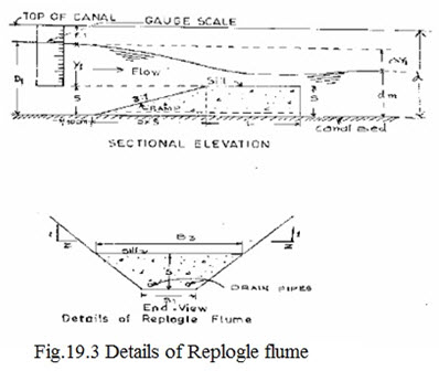
The gauge is located at a distance of 30 cm upstream of the ramp and its Zero must coincide with the sill level. The discharge equation, which consists critical flow area and critical depth is complicated due to the trapezoidal shape of flow area and hence is not given here. However, in Table-19.4, discharge are given for corresponding gauge (Y1) for three sets of sill heights (S) and sill lengths (L) for a channel with bottom width of 30 cm and side slopes 0.5 : 1, 1 : 1, 1.5 : 1 and 2 : 1.
Modular Limit:
The sill height (S) is the most important design dimension for which the flume is very sensitive. Replogle flume operates satisfactorily upto 85% submergence i.e. the downstream water head should not be more than 85% of the upstream water head, both measured above the sill level. In other words loss of head ΔY1 should be least 15% of the gauge reading Y1. Care must be taken that the sufficient free board is available to accommodate upstream depth D1 (d1 = s + Y1) for the maximum designed discharge.
TABLE - 6.4 Discharge for Replogle Flumes in Field Channels
|
Discharge Q (lps) |
Gauge Reading Y1 (cm) Channel Side Slope |
|||
|
0.5:1.0 |
1.0:1.0 |
1.5:1.0 |
2.0:1.0 |
|
|
6 |
3.8 |
3.0 |
2.5 |
2.2 |
|
8 |
4.5 |
3.6 |
3.1 |
2.7 |
|
10 |
5.2 |
4.2 |
3.5 |
3.1 |
|
12 |
5.9 |
4.7 |
4.0 |
3.5 |
|
14 |
6.5 |
5.2 |
4.4 |
3.8 |
|
16 |
7.0 |
5.6 |
4.8 |
4.2 |
|
18 |
7.6 |
6.0 |
5.1 |
4.5 |
|
20 |
8.1 |
6.5 |
5.5 |
4.8 |
|
22 |
8.6 |
6.8 |
5.8 |
5.1 |
|
24 |
9.0 |
7.2 |
6.1 |
5.4 |
|
26 |
9.5 |
7.6 |
6.5 |
5.7 |
|
28 |
9.9 |
7.9 |
6.8 |
5.9 |
|
30 |
10.4 |
8.3 |
7.0 |
6.2 |
|
32 |
10.8 |
8.6 |
7.3 |
6.4 |
|
34 |
11.2 |
8.9 |
7.6 |
6.7 |
|
36 |
11.6 |
9.3 |
7.9 |
6.9 |
|
38 |
12.0 |
9.6 |
8.1 |
7.2 |
|
40 |
12.3 |
9.9 |
8.4 |
7.4 |
|
42 |
12.7 |
10.2 |
8.6 |
7.6 |
|
44 |
13.1 |
10.4 |
8.9 |
7.8 |
|
46 |
13.4 |
10.7 |
9.1 |
8.0 |
|
48 |
13.8 |
11.0 |
9.4 |
8.2 |
|
50 |
14.1 |
11.3 |
9.6 |
8.5 |
|
52 |
14.4 |
11.5 |
9.8 |
8.7 |
|
54 |
14.7 |
11.8 |
10.1 |
8.8 |
|
56 |
15.1 |
12.0 |
10.3 |
9.0 |
|
58 |
15.4 |
12.3 |
10.5 |
9.2 |
|
60 |
15.7 |
12.5 |
10.7 |
9.4 |
Advantages:
− Simple in construction and cheap in cost
− No upstream approach transition is required as the section of the flume is same as the section of the channel
− Modular limit (free flow limit) is higher (upto 85%) the Parshall flume and Cut-throat flume.
Replogle Flume for Field Channels:
Recommended size of Replogle flume for the measurement of discharge in field channels (Bottom width B1 = 0.3 m) is with sill S as 0.2 m and sill length L as 0.5 m. The discharge table, for channel side slopes 0.5:1.0, 1.0:1.0, 1.5:1.0, 2.0:1.0 and is given in Table-6.4.
Construction:
Replogle flume can be constructed either in masonry or in concrete. But care must be taken to provide accurate side slopes throughout the length of flume, finishing, curing, etc. the sill height (S) should not change more than 1 percent. Wall Mounted Gauge scale is mounted on the sidewall of the channel at the prescribed location. As sidewalls of the channel are inclined, scale should be either calibrated to read vertical depths, or correction factor should be applied.
Last modified: Tuesday, 18 February 2014, 8:23 AM