Site pages
Current course
Participants
General
MODULE 1. Introduction to production of agricultur...
MODULE 2. Advance in material for tractor and agri...
MODULE 3. Advanced manufacturing techniques
MODULE 4. Heat treatment of steel
MODULE 5. Industrial lay out planning and quality ...
MODULE 6. Economics of process
MODULE 7. Techno economic feasibility of project r...
MODULE 8. Servo motors, drives and controllers
MODULE 9. CNC controllers for machine tools
MODULE 10. CNC programming
MODULE 11. Assembly and plant automation storage a...
LESSON 4. CUTTING TOOLS FOR CNC MACHINES
4.1 Introduction
Cutting tools are available in three basic material types: high-speed steel, tungsten carbide, and ceramic. High-speed steel is generally used on aluminum and other nonferrous alloys, while tungsten carbide is used on high-silicon aluminums, steels, stainless steels, and exotic metals. Ceramic inserts are used on hard steels and exotic metals. Inserted carbide tooling is becoming the preferred tooling for many CNC applications. For the full utilization of CNC machines it is essential to pay due attention to the selection and usage of tooling, namely tool holders, cutting tools and work holding devices. The tools for CNC machines must be quickly changeable to reduce non-cutting time, preset and reset outside the machine, high degree of interchangeability, increased reliability and high rigidity.
4.2 Classification of cutting tools
The cutting tools can be classified on the basis of setting up of tool, tool construction and cutting tool material:
On the Basis of Setting up of Cutting Tool
(a) Preset tools.
(b) Qualified tools.
(c) Semi qualified tools.
On the Basis of Cutting Tool Construction
(a) Solid tools.
(b) Brazed tools.
(c) Inserted bit tools.
On the Basis of Cutting Tool Material
(a) High speed steel (HSS).
(b) High carbon tool steel (HCS).
(c) Cast alloy.
(d) Cemented carbide.
(e) Ceramics.
(f) Boraon Nitride.
(g) Diamond.
(h) Sialon.
4.2.1 Preset Tools
The setting of tools in advance at a place away from the machine tool or offline, in special holders is known as preset tools. A presetting device is used to preset axial and radial positions of the tool tip on the tool holder. Once this is done, the tool holder is ready to be mounted on the machine and produce a known dimension. Presetting devices to various levels of sophistication are available like optical projector. Tool length and tool diameter compensation facilities available in the present day CNC machines have brought down the importance of presetting. Since the generation of actual geometry is taken care of by the CNC part program, which is essentially the coordinates through which the cutting tool tip moves, it is important to know the actual dimensions of the tool when it is placed in the spindle. The relationship of the tool with reference to the tool holding mechanism requires a special attention during CNC machining process. The actual point to be programmed in a CNC part program is the tip of the tool whereas the axes will be moving with respect to a known point in the spindle, e.g. the centre of the spindle in case of machining centres. It becomes therefore necessary to know precisely the deviation of the tool tip from the gauge point on the spindle.
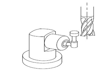
Fig. 4.1 Tool Offset Determination in CNC Machines
4.2.2 Qualified Tools
Tool which fits into a location on the machine, where its cutting edge is accurately positioned within close limits relative to a specified datum on the tool holder or slide, is known as qualified tool. The cutting tools satisfy the following requirements:
(a) Tools need not be measured individually.
(b) No presetting device is used.
(c) The dimensions of the tool holder which are fixed and known.
(d) Set up time is reduced.
(e) Control dimensions of the tool are nominal and fixed.
(f) Higher control on resharpening e.g. drills, reamers.
(g) Cutter for better size control e.g. end mills, teamers.
(h) Chip breaking facilities incorporated in tool.
(i) Impoved designs.
The qualified tool with holder shown in Figure 4.2
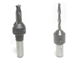
Countersink Drill Bit
Fig. 4.2 Qualified Tooling for CNC Machines
4.2.3 Semi-qualified Tools
The qualified tools which can be adjusted to the dimensions by using several adjustable buttons on the tool shank are known as semi qualified tools. These tools demand regular maintenance and calibration for accurate dimensioning.
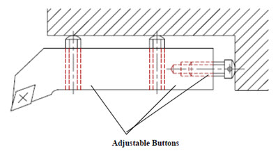
Fig. 4.3 Semi-qualified Tooling for CNC Machines
4.2.4 Solid Tools
Solid tools are usually made of High Speed Steel or High Carbon Steel. These tools are used on high speeds with sufficient quantity of cutting fluid to get good suface finish and longer tool life.
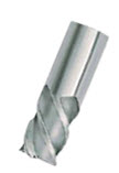
Fig. 4.4 Solid Tool
4.2.5 Brazed Tools
A forged shank of high strength steel with belt of high speed steel, tungusten carbide stellite brazed to the shank on the cutting edge.
4.2.6 Inserted Bit Tools
The tools with indexible inserts of harder and special grade carbide/ceramic materials. A wear resistant layer of Titanium nitride of Titanium carbide is coated on the insert it reduces the cost of tool. Inserts can be easily removed from the tool holder. So tool changing time and cost of machining are less.
4.2.7 High Speed Steel
The H.S.S. is carbon steel to which alloying elements like tungusten, chromium, vanadium, cobalt and molyblemum to be added to increase their hardness and wear resistance.
4.2.8 High Carbon Tool Steel
High carbon tool steel is suitable for low cutting speeds and low temperatures. The hardness of this tool is determined by the carbon contents.
4.2.9 Cast Alloy
This is a non ferrous alloy and gives high machining performance than that of H.S.Steel. Its hardness and toughness are high at higher temperatures.
4.2.10 Cemented Carbides
It contains 5% carbon, 13% cobalt and 81% tungsten. This tool is widely used in modern costly machines as tip tools. The tool setting time is reduced.
4.2.11 Ceramics
It can be used for higher cutting speed, superior surface finish and great machining flexibility. The Aluminum oxides, boron carbides, silicon carbide, titanium borides and titanium carbides are known as ceramics.
4.2.12 Boron Nitride
(a) High wear resistance.
(b) Used for machining hardened steel and high temperature alloys.
4.2.13 Diamond
(a) Low friction and high wear resistance.
(b) Good cutting edge.
(c) Single crystal diamond is used to machine copper to a high surface finish.
4.2.14 Sialon
Used for machining aerospace alloys.
4.3 Design Features of CNC Tooling
In general the following points are to be considered while designing of CNC tooling:
(a) To give High accuracy.
(b) For variety of operations.
(c) Interchangeability to produce same accuracy.
(d) Flexibility.
(e) Rigidity of tooling to withstand cutting forces.
(f) Rigidity to transmit the power at higher speeds.
(g) Quick changing of tools to keep the down time minimum.
4.4 Work Holding Devices for CNC Machines
In the CNC machines, fixtures are still required to locate and hold the work pieces while machining. The work holding devices should have the following uniqueness:
a) Work holding devices must have required accuracy and must have matching reference surfaces with the reference system.
b) Work holding devices are allowed to perform a number of operations on different faces in a single setting.
c) Work holding devices must enable quick loading and unloading.
d) Work holding devices must be fool-proofing to avoid incorrect loading of the job.
e) Work holding devices must be sufficient rigidity to fully withstand the cutting forces.
f) Work holding devices must be safe in use and loading and unloading.
g) Work holding devices must have a sufficient of clamping force for use of full roughing cuts.
h) Work holding devices must be simple in construction maximum as possible.
Automatic pallet changes over systems are used in modern CNC machines. These pallets simply move for interchanging their positions on the machine table. While machining is being done on a job kept on one pallet, the other pallets are accessible to the operator for clamping and unclamping raw material or finished product. This saves a lot of material handling and set up time, resulting in higher productivity.
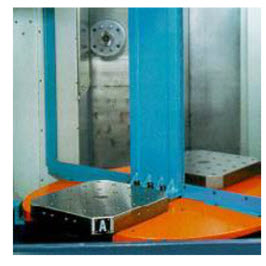
Fig. 4.5 Automatic Pallet Changer
4.5 Automatic Tool Changer
The CNC machines are designed to perform a number of operations in a single setting of the job. A number of tools may be required for making a complex part. In a manual machine, the tools are changed manually whenever required. In a CNC machine, tools are changed through program instructions. The tools are fitted in a tool magazine or drum. When a tool needs to be changed, the drum rotates to an empty position, approaches the old tool and pulls it. Then it again rotates to position the new tool, fits it and then retracts. This is a typical tool changing sequence of an automatic tool changer (ATC).
The concept of the ATC is that the range of tools for a specific job shall be made available for automatic selection and positioning. ATC cab be
Drum Type: For holding small number of tools usually not more than 30, Stored on periphery of drum and tool search speed is faster.
Chain Type: For more number of tools (40 or more), tools search speed is less.
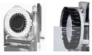
Figure 4.6 Drum Type Automatic Tool Changer (ATC)
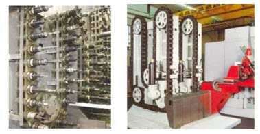
Fig. 4.7 Chain Type Automatic Tool Changer (ATC)
As soon as the tool selection command is received by the system, the selected tool comes to a fixed place known as tool change position. The selected tool is transferred to the spindle from magazine after the previous tool is transferred to the magazine from spindle. This is called tool change cycle.
4.5.1 Automatic Tool Changer Advantages
(a) Lines changed in seconds instead of hours.
(b) Increase operator safety by changing tools automatically.
(c) Change tools in seconds for maintenance and repair.
(d) Increase flexibility.
(e) Heavy and large multi-tools that are automatically exchanged.
Reference: http://www.ignou.ac.in/upload/Unit-5-57.pdf.
Last modified: Tuesday, 29 April 2014, 9:06 AM