Site pages
Current course
Participants
General
Module 1. Design and operational parameters
Module 2. Performance evaluation and maintenance a...
Module 3. Performance evaluation and maintenance a...
Module 4. Performance evaluation and maintenance a...
Module 5. Performance evaluation and maintenance a...
Module 6. Performance evaluation and maintenance a...
Module 7. Biodiesel utilization in CI engines
Lesson 7. Gasifier parts and accessories
1. Gasification
Gasification is the process in which the supply of oxygen is controlled and the raw materials are converted into chemical product called producer gas. This process transfers the majority of the chemically bound energy of the solid fuel into the gas phase. The oxygen supply will be 20 to 40 per cent of the stochiometric air requirement. In combustion process, raw materials are directly converted into heat energy, where as in gasification process, raw materials are converted into an intermediate chemical product, which constitutes mainly of carbon monoxide and hydrogen.
The calorific value of producer gas is 950-1200 kcal m-3. The main components of producer gas are carbon monoxide (18-24%), hydrogen (18-20%), carbon dioxide (9-12%), nitrogen (45-55%), methane (1-5%) and water vapour (4%).
In gasification, the solid fuel is subjected to a series of thermochemical processes like drying, pyrolysis, oxidation and reduction. The resultant product is producer gas. It has the thermochemical conversion efficiency of about 70 to 90 per cent.
2. Gasifier
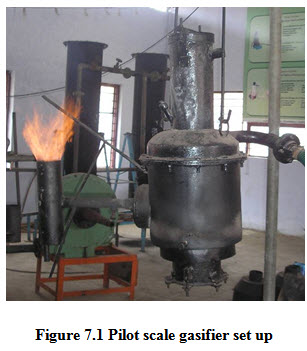
Gasifiers are used to convert the solid fuel materials into producer gas. Based on the mode of travel of fuel and air supply, the gasifiers are broadly classified into down draft gasifiers, updraft gasifiers and cross draft gasifiers. Though there are various thypes of gasifiers are employed for gasification of various types of fuel materials, the basic components of a gasifier are same. They are reactor, air supply system, feeding system, gas outlet system, grate, ash removal system etc. In this chapter the significance of every system of gasifier is discussed.

Reactor
The configuration of reactor is an important aspect in deciding sufficiently high residence time of the biomass to provide good carbon conversion. The reactor diameter decided based on the feed rate of the fuel materials, residence time of the material, air flow rate etc. However, in general the specific gasification rate for gasifiers is considered to be 175 – 225 kg h-1 m-2. Based on the feed rate and feed material, the cross-sectional area of the reactor may be decided. Accordingly the height of the reactor is also calculated for the given volume of the feed material. Generally the reactor is made up of MS of suitable thickness to withstand the higher temperature attained during gasification.
Feeding system : Feeding is normally from the top of the gasifier for majority of the gasifier systems. Suitable feeding system has to be arranged based on the nature of materials, size of feed, bulk density of feed etc. For higher capacity gasifiers, mechanical system of feeding may be arranged.
Air flow system : Air flow is calculated based on the stochiometric air requirement for specific feed materials. The equivalence ratio between 0.2 to 0.4 will be assessed for bette gasification yield. Accordingly the blower type, capacity will be decided for the supply of calculated amount of air to the gasifiers. For the uniform supply of required air to the oxidation zone, suitable air distribution systems such as tuyers may be used and hence the oxygen supply can be assured for better gasification.
Grate : Grate is the assembly which separates the ash released during the gasification process. The grate opening should be selected in such as way that it should not allow the flow of feed materials but assure a proper ash removal. If needed, mechanical systems are employed for the proper removal of ash immediately after formation. Proper removal of air helps in proper flow of feed materials, better and uniform air supply during gasification and avoids formation of clinkers in suitable environment.
Gas out let : The gas outlet system should consider the direction of flow of producer gas. Feed materials with higher moisture content or tar release are used for gasification and if the producer gas passes though the materials, the quality of the gas will be affected. Hence, the gas produced after reduction zone has to be immediately taken out for further applications.
Gas cleaning system : The outlet producer gas consists of particulate matters, tar particles, moisture as impurities. For thermal applications the impurities may not have much problem. However, the tar can be removed easily after condensation in the outlet pipe during its transit. For engine applications, the gas should be free from all the foreign materials, otherwise it will affect the performance of the engine and further that will damage the engine.
Hence, the gas cleaning systems are employed at different stages to remove the impurities. They are:
Cyclone : Coarse particles are separated from the gas stream in a high efficiency cyclone separator. Entrained particles in the producer gas are collected in a separate bin at the bottom of the cyclone assembly and can be cleaned periodically.
Impingement separator : Intermediate size particles and most of the fines are removed from the gasifier in an impingement separator. This separator is insulated so as to avoid condensation of vapours and to allow passage of hot gas (above 150°C) to the glass fibre cloth filter.
Glass fibre cloth filter : To guard the engine against any solid material, the product gas is passed through a glass fibre cloth filter, which removes any solids that have slipped through the previous filter sections.
Cooler : The cooling section consists of a tubular heat exchanger. Condensate can be tapped from the cooler by drain vessels, equipped with safety taps. Cooler outlet temperatures vary between 30° and 50°C, depending on environmental conditions (temperature, wind) and engine load.