Site pages
Current course
Participants
General
MODULE 1. Fundamentals of Soil Mechanics
MODULE 2. Stress and Strength
MODULE 3. Compaction, Seepage and Consolidation of...
MODULE 4. Earth pressure, Slope Stability and Soil...
Keywords
LESSON 9. Shear Strength of Soil
9.1. Shear Resistance
Sliding between the particles during loading is a major factor for deformation of soil. The resistance that the soil offers during deformation is mainly due to the shear resistance between the particles at their contact points. Figure 9.1 shows the two particles in contact which is similar to the contact between two bodies. The normal force (N) is perpendicular the contact surface and shear force (t) is tangential force parallel to the contact surface. During sliding between two bodies, the maximum shear force can be written as:
\[{\tau _{\max }}=\mu N\] (9.1)
where μ is the coefficient of friction. In case of soil particles, the maximum shear force can be written as:
![]()
where ø is the angle in internal friction of soil.
9.2 Mohr Circle
At any stressed point, three mutually perpendicular planes exist on which shear stress is zero. These planes are called principal planes. The normal stresses that act on these planes are called principal stress. The largest principal stress is called major principal stress (σ1), the lowest principal stress is called minor principal stress (σ3) and the third stress is called intermediate stress (σ2). The corresponding planes are called major, minor and intermediate plane, respectively. The critical stress values generally occur on the plane normal to the intermediate plane. Thus, only σ1 and σ3 are considered. Figure 9.2 shows an element and direction of σ1 and σ3. The major and minor principle planes are also shown. The major and minor principle planes are horizontal and vertical direction, respectively. The normal stress and shear stress at any plane making and angle q with horizontal can be determined analytically as:
\[\sigma={{{\sigma _1} + {\sigma _3}} \over 2} + {{{\sigma _1} - {\sigma _3}} \over 2}\cos 2\theta \] (9.3)
\[\tau={{{\sigma _1} - {\sigma _3}} \over 2}\sin 2\theta\] (9.4)
The stresses can be determined by graphically using Mohr Circle as shown in Figure 9.2. Mohr Circle is drawn in normal (σ) and shear (t) axis. The compressive normal stress is considered as positive. The shear stress that produces anti-clockwise couples on the element is considered as positive. The circle is drawn by taking O [(σ1 +σ3)/2, 0] as center and (σ1 -σ3)/2 as radius (as shown in Figure 9.2). Now from (σ3, 0) point draw a line parallel to AB plane. The line intersects the Mohr Circle at a point whose coordinates represents the normal and shear stress acting on AB plane [D(σ, t)]. The A (σ3, 0) point is called pole or the origin of plane.
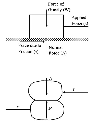
Fig. 9.1. Two particles/bodies in contact.
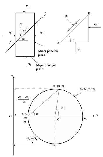
Fig. 9.2. Mohr Circle.
References
Ranjan, G. and Rao, A.S.R. (2000). Basic and Applied Soil Mechanics. New Age International Publisher, New Delhi, India.
Suggested Reading
Ranjan, G. and Rao, A.S.R. (2000) Basic and Applied Soil Mechanics. New Age International Publisher, New Delhi, India.
Arora, K.R. (2003) Soil Mechanics and Foundation Engineering. Standard Publishers Distributors, New Delhi, India.
Murthy V.N.S (1996) A Text Book of Soil Mechanics and Foundation Engineering, UBS Publishers’ Distributors Ltd. New Delhi, India.
Last modified: Monday, 23 September 2013, 8:47 AM