Site pages
Current course
Participants
General
MODULE 1. BASIC CONCEPTS
MODULE 2. SYSTEM OF FORCES
MODULE 3.
MODULE 4. FRICTION AND FRICTIONAL FORCES
MODULE 5.
MODULE 6.
MODULE 7.
MODULE 8.
LESSON 8. MOMENT OF INERTIA
8.1 INTRODUCTION
As per Newton’s first law of motion, it is the property of a matter by virtue of which it offers resistance to any change in its state is called Inertia. Usually, the moment of inertia refers to the mass moment of inertia. On the other hand, the moment of inertia of an area refers to the resistance of the cross-sectional area to bending or flexure. It represents the flexural strength of a cross-sectional area. The flexural strength is expressed in terms of bending formula given by
\[{M \over I}\] = \[{\sigma\over y}\] (8.1)
Where M is bending moment, I is the moment of inertia of the section about the axis of bending called neutral axis (axis at which the bending stress is zero), σ is the bending stress at any element at distance y from neutral axis. Equation (11.1) can be written as
\[\sigma\] = \[{M \over I}\] × y (8.2)
Equation (8.2) indicates the larger the moment of inertia of an area, the smaller the bending stress, which signifies more rigidity.
Fig.8.1 Moment of Inertia
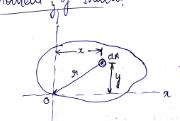
The moment of inertia of an area about x and y axes as shown in Figure 8.1 are defined by
Ix = ∫y2dA (8.3a)
Iy = ∫x2dA (8.3b)
Where dA is the area of an element x, y stands for distance of the element from y and x axes respectively. Moment of inertia of an area is expressed as fourth power of the distance, that is cm4, mm4 or m4.
In case of shafts subjected to torsion or twisting moment, the moment of inertia of the cross-sectional area about its centre O is considered. This moment of inertia about 0 is called polar moment of inertia or moment of inertia about pole. It is denoted by J. The problems in which J is used are cylindrical shafts subjected to torsion, slabs subjected to rotation etc. The polar moment of inertia is given by
J = ∫r2 dA (8.4)
Where r is the distance of an element area from O.
8.2 MOMENT OF INERTIA OF GEOMETRICAL FIGURES USING METHOD OF INTEGRATION
8.2.1 Rectangular Area
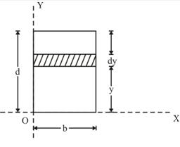
Fig. 8.2 Moment of inertia of a rectangular area
Consider an elemental strip of width b and thickness dy in a rectangular area as shown in Fig.8.2 . Area of the element and its centroidal coordinates from x and y axes are given as
dA = b × dy
x = \[{b \over 2}\]
y = y + \[{dy \over 2}\]
Here dy/2 is very small and hence neglected. Substituting these values in Eq. (8.3a), the moment of inertia of rectangular about x-axis is determined as
Ix = ∫y2 dA = ∫y2 bdA
Integrating between the limits of y from 0 to d, yields
Ix = \[\smallint\limits_0^d b{y^2}dA\] = \[{{b{d^3}} \over 3}\]
Ix = \[{1 \over 3}\] bd3 (8.5)
Similarly, moment of inertia of rectangular about y-axis is
Iy =\[{1 \over 3}\] db3 (8.6)
8.2.2 Triangular area
Consider a triangular plane area of base width b and height d as shown in Fig.8.3. From the similar triangles ACD and AOB, the width CD of the element can be written as
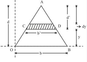
Fig.8.3 Moment of inertia of a triangle about its base
The area of the elemental strip (shown hatched) is
dA = bꞌ × dy = \[{b \over d}\left( {d - y} \right)dy\]
The moment of inertia of the triangular area about x-axis (base of the triangle) is determined by
Ix = ∫y2 dA = ∫y2 \[{b \over d}\left( {d - y} \right)dy\]
Integrating between the limits of y from 0 to d, gives
Ix = \[{b \over d}\smallint \limits_0^d \left( {d - y} \right){y^2}dy\]
Ix = \[{b \over d}\left[ {{{d{y^3}} \over 3} - {{{y^4}} \over 4}} ]\] = \[{b \over d}\left[ {{{{d^3}} \over 3} - {{{d^4}} \over 4}} ]\]
Ix = \[{{b{d^3}} \over {12}}\] (8.7)
8.2.3 Circular Area
Consider a circular area of radius R as shown in Fig.8.4(a) and 4(b), with an elemental area as indicated by shaded part. Fig.8.4(b) gives the enlarged view of the element ABCD.
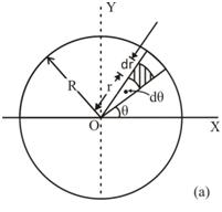
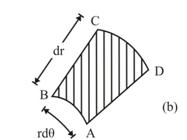
Fig.8.4 Moment of inertia of a circle
The area of the element,
dA = Area of ABCD
= arc length AB × BC
dA = rdӨ × dr
The centroidal coordinates of the element from x and y axes are given as
x = \[\left( {r + {{dr} \over 2}} \right)cos\left( {\theta+ {{d\theta } \over 2}}) \approx rcos\theta\]
and
y = \[\left( {r + {{dr} \over 2}} \right)sin\left( {\theta+ {{d\theta } \over 2}}) \approx rsin\theta\]
Using Eq. (8.3), the moment of inertia of circular area about x and y axes are determined as:
Ix =∫y2 dA = ∫r2 sin2Ө × rdӨ ×dr
Ix = ∫r3 dr × ∫sin2ӨdӨ
With the integration limits of r from 0 to R and Ө from 0 to 2П results
and Iy = ∫x2 dA = ∫r 2 cos2Ө × rdӨ ×dr
As both x and y axes pass through the centroid of the circular area, Equations (8.8a) and (8.8b) give the moment of inertia of circle about its centroidal axes.
The above concept can be extended to obtain the moment of inertia of semicircular and quarter circular area as given below.
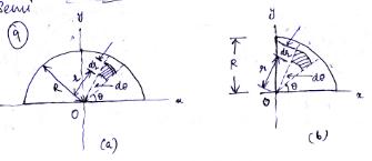
Fig.8.5 Moment of inertia of : (a) semicircle, and (b) quarter circle
Moment of inertia of semicircular area about x and y axes is
Ix = Iy = \[{{{R^4}} \over 8}\] (8.9)
Moment of inertia of quarter circular area about x and y axes is
Ix = Iy = \[{{{R^4}} \over 16}\] (8.10)
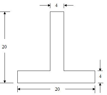
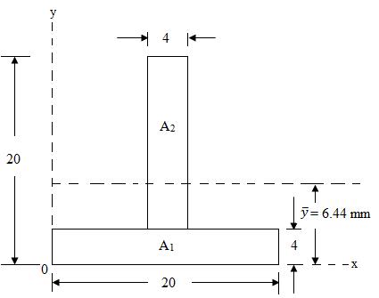
Example: A T-section is 20×20×4 as shown in Figure. Calculate the moment of inertia of the section about the x-x axis parallel to the base of T-section passing through its centroid.
(a) (b)
(all dimensions are in mm)
Fig. 8.6
Sol: The given T-section is symmetrical about the y-y axis. Therefore, \[\bar x = {{20} \over 2}\] = 10mm
For finding ,
\[\bar y = {{\sum {A_i}{y_i}} \over {\sum {A_i}}}\] = \[{{928} \over {144}}\] = 6.44mm
The moment of inertia of the entire area about the centroidal x-x axis is given by
Ixx = \[[ {{{20 \times {4^3}} \over {12}} + \left( {20 \times 4}){{\left( {4.44} \right)}^2}}] + \left[ {{{4 \times {{16}^3}} \over {12}} + \left( {4 \times 16} \right){{\left( {5.56} \right)}^2}} \right]\]
= [10667 + 1577.09] + [1365.33 + 1978.47]
= 12244.09 + 3343.8
= 15587.89 mm4
Example: Determine the moment of inertia about the horizontal axis passing through the centroid of the section as shown in Fig.7.
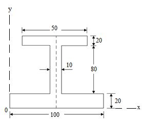
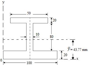
(a) (b)
(all dimensions are in mm)
Fig.8.7
Sol: The given I-section is symmetrical about the y-y axis, therefore,
\[\bar x = {{100} \over 2}\] = 50 mm
To find \[\bar x\] , we have to divide the whole Figure into standard areas.
Example: Find the moment of inertia of a plate with a circular hole about its centroidal x axis as shown in Fig.8.
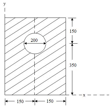
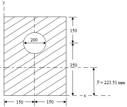
(a) (b)
(all dimensions are in mm)
Fig.8.8
Sol: The given plate is symmetrical about the y-y axis, therefore \[\bar x\] = 150 mm.
To find , \[\bar y\]