Site pages
Current course
Participants
General
Module- 1 Scope and importance of food processing....
Module- 2 Processing of farm crops; cereals, pulse...
Module- 3 Processing of animal products
Module- 4 Principal of size reduction, grain shape...
Module- 5 Theory of mixing, types of mixtures for ...
Module- 6 Theory of separation, size and un sized ...
Module- 7 Theory of filtration, study of different...
Module- 8 Scope & importance of material handl...
Lesson. 20 Theory of Separation
Theory of Separation
Separation techniques are involved in a great number of food processing industries and represent an everyday important unit operation of practising food process engineering. Separation techniques are defined as those operations that isolate specific ingredients of a mixture without a chemical reaction taking place.
Screening and size & un-sized separation
Screening is a separation technique of a mixture of various sizes of solid particles into several fractions, based on size and shape difference. It consists of forcing the mixture through a screen of a specific size aperture. Small capacity plane screens are often called as sieves. By vibrating or oscillating a screen, particle smaller than a given aperture pass through, thus being separated from the remaining mixture.
Screens are made from metal bars, perforations or slotted metal plates, woven wire cloth, or fabric, such as silk bolting cloth. Metals used include steel, stainless steel, bronze, copper, nickel, and monel. The screen surface may be plane (horizontal or inclined) or it may be cylindrical. The aperture size of the screens ranges from about 0.1 to 250 mm, with exceptional cases in which the aperture may be as large as 460 mm. The material passing through a given screen is termed undersize, fines or minus (−) material, while the material retained in a given size screen is called oversize, tails or plus (+) material. Either stream may be the desired (product) stream or the undesired (reject) stream. Screening has two main applications: (1) laboratory technique for particle size analysis, and (2) Industrial operation for fractionation and classification of particulate solids.
Every screen is identified in meshes per inch. In coarse screens, the term mesh refers to the distance between adjacent wires. While in fine screens, the mesh is the number of opening per linear inch counting from the centre of any wire to a point exactly one inch distant (e.g., a 200 mesh screen will have 200 opening per linear inch). Screen aperture or Screen size opening is, defined as the minimum clear space between the edges of the opening in the screening surface. For carrying out screen analysis, Tyler standard screen series is used as test sieves. This testing sieves are constructed of woven wire screens with square openings, the mesh and dimension of which are standardised.
Tyler standard screen series is based on a 200 mesh screen with a wire 0.053 mm (0.0021 in) in diameter, giving a clear opening of 0.074 mm (1/200 – 0.0021 = 0.0029 in). The screen coarser than 200- mesh have their mesh and wire diameter so adjusted that the area of opening in any one screen is approximately twice the area of the opening in next consecutive finer screen. This means that the ratio of linear size of opening in any screen to that in the next finer screen is (1.414). Therefore, a 150-mesh screen will have an opening of 0.104 mm ( × 0.0029 = 0.0041 in) with a wire of 0.064 mm (1/150 – 0.0041 = 0.0026 in) diameter. These testing sieves are used to determine the efficiencies of screening equipments.
Theory of filtration
In filtration, suspended solid particles in a liquid are physically or mechanically removed with help of a porous medium that retains the particles as a separate phase or cake and passes the clear filtrate.
In filtration a pressure difference is set up and causes the fluid to flow through the small holes of a screen or cloth which block the passage of large solid particles, which in turn, build up on the cloth as a porous cake. The valuable product may be the clear filtrate from the filtration, or the solid cake, or both. Sometime it is neither, as when the waste solids must be separated from waste liquid prior to disposal. In some cases complete removal of solid particles is required and in other cases only partial removal. Commercial filtration ranges from simple straining to highly complex separations. The volume of suspensions to be handled may vary from extremely large quantities (in water purification) to relatively small quantities (in the fine chemical industry). Often the feed is modified by pre-treatment to increase the filtration rate, as by heating, recrystallizing, or adding a ‘filter aid’ such as cellulose or diatomaceous earth.
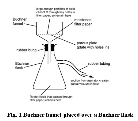
Suspension flows through a filter medium by virtue of a pressure differential across the medium. Therefore, filters are also classified into those that with a pressure above atmospheric on the upstream side of the filter medium and those that operates with atmospheric pressure on the upstream side and a vacuum on the downstream side. Pressure above atmospheric may be develop by the force of gravity on a column of liquid, by a pump or blower, or by centrifugal force. A typical laboratory filtration apparatus (Buchner funnel placed over a Buchner flask) is shown in Fig. 1. The slurry containing liquid and suspended solids is caused to flow through the filter paper placed over a porous plate by a vacuum on the exit end. The solid particles are blocked by the small opening in the pores of the filter paper and build up in form a porous cake as the filtration proceeds. This cake itself also act as a filter for the suspended particles and as the cake builds up, resistance to flow also increases.
Different types of filter
Filtrations are classified mainly into two types
(i) Cake filtration and (ii) Deep bed filtration
In case of cake filtration, the suspension contains relatively a larger percentage of solid, so that a cake is formed and can subsequently be detached from the filter medium. In case of deep bed filtration, the proportions of suspended solids is very small and the particle of solid being smaller than the pores of a filter medium will penetrate a considerable depth and ultimately get trapped inside the filter medium and usually no layer of solids will appear on the surface of the medium (e.g. water filtration).
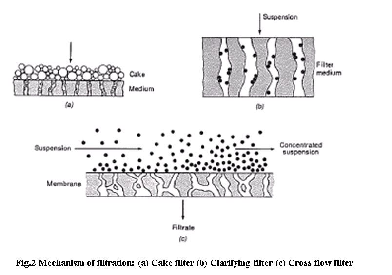
Accordingly, filters are divided into three main groups, cake filters, clarifying filters and cross flow filters. Cake filters separates relatively large amounts of solids as a cake of crystals whereas clarifying filters removes small amounts of solids to produce a sparkling clear liquid such as beverages (Fig.2a).
The solids are trapped inside the filter medium or on its external surfaces. Clarifying filters differ from screens in that the pores of the filter medium are much larger in diameter than the particles to be removed (Fig. 2b). In a cross flow filter the feed suspension flows under pressure at a fairly high velocity across the filter medium (Fig.2c). A thin layer solid may form on the surface of the medium, but high speed liquid keeps the layer from building up. The filter medium is a ceramic, metal, or polymer membrane with pores small enough to exclude most of the suspended particles. Some of the liquid passes through the medium as clear filtrate, leaving a more concentrated suspension behind.
Principle of cake filtration and rate of filtration
In cake filtration, the feed to be handled (two phase mixture) is termed as slurry, the bed of deposited solids on a porous membrane (filter medium) is termed as cake and the clear liquid leaving the filter medium is term as filtrate.
During the initial period of flow, solid particles are trapped within the pores of a medium forming the true filter medium. The liquid passes through the bed of the solids and through the filter medium. Initially, rate of filtration is high. As the solids are removed from the feed, they accumulate in the filter medium, resulting in an increase resistance to flow and the rate of filtration decreases for a given pressure differential across the filter medium.
The rate at which the filtrate is obtained in a filtration operation, i.e., the rate of filtration depends upon the following factors
Pressure drop across the filter medium
The area of the filtering surface
The viscosity of the filtrate
The resistance of the filter cake as determined by the solids removed from slurry
The resistance of the filter medium
The rate of filtration can be written as follows
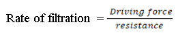
where the driving force is the pressure required to move the fluid through the filter medium and the resistance is dependent on several factors. The overall resistance can be describe by following expression
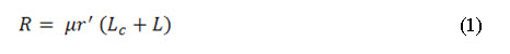
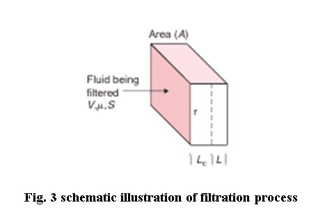
where Lc represent the thickness of accumulated solids in the filter cake, µ is the fluid viscosity and L is the fictitious thickness of the filter medium. The parameter r' represents the specific resistance of the filter cake and it is a property of particles forming the filter cake.Lc is described by
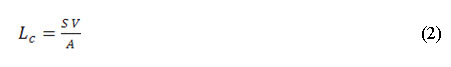
where S is the solid content of the fluid being filtered, and V is the volume that has passed through the filter with cross-sectional area (A).
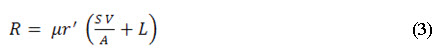
The thickness of the filter cake represents a fictitious value to describe the total thickness of all solids accumulated. In some filtration processes, this may approach the real situation. Utilizing Equations (1) and (2), the total resistance can be written in the following manner:
Thus, expression for rate of filtration is obtained as follows
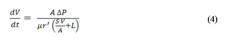
The filtration process may occur in two phases:
(1) Constant rate filtration, normally occurs during early stages of the process, and
(2) Constant pressure filtration, occurring during final stages of the process
Pressure drop during filtration
With the help of the pressure difference applied between the slurry inlet and the filtrate outlet, the filtrate is forced through a filter. The filtrate has to pass through three resistances in series:
(1) Resistance of the feed and filtrate channel,
(2) Resistance of the cake and
(3) Resistance offered by the filter medium
The overall or total pressure drop over the filter at any time is equal to the sum of the individual pressure drops over the medium and cake.
Constant rate filtration
Constant-rate filtration is described by the following integrated forms of Equation (4), which can be used to determine the required pressure drop as a function of the filtration rate:
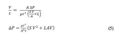
Equation (5) can be expressed in a different form if the thickness (L) of the filter medium is considered negligible. The following equation for pressure drop as a function of time is obtained
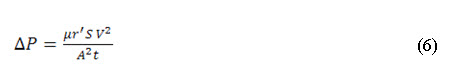
In many situations, Equation (6) can be used to predict pressure drop requirements for a filter during the early stages of the process.
Constant pressure filtration
An expression for describing constant pressure filtration can be obtained from the following form of Equation (4):
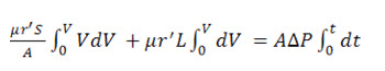
Integrating above Equation leads to following equation:
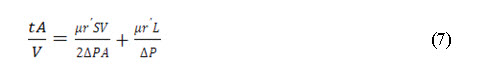
or the following equation if filter medium thickness (L) can be assumed to be negligible:
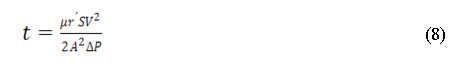
Essentially, Equation (8) indicates the time required to filter a given volume of feed slurry when a constant pressure is maintained.
Reference to Equation (4) reveals that the filtration process is directly dependent on two factors: the filter medium and the fluid being filter. In Equation (4) a filter medium is described in terms of area (A) and the specific resistance ( ). The filter medium will depend considerably on the type of fluid being filtered. In the case of liquid filtration, the filter medium, to a large extent, will contain the solids removed from the liquid. This filter cake must be supported by some type of structure that plays only a limited role in the filtration process. In some cases, these supporting materials may be woven (wool, cotton, linen) or they may be granular materials for particular types of liquids. In any case, the primary role of the material is to support the collected solids so that the solids can act as a filter medium for the liquid.
The second factor of Equation (4) that influences filtration rate is the fluid being filtered as described by the fluid viscosity (μ). The rate of filtration and the viscosity of the fluid being filtered are inversely related; as the viscosity of the fluid increases, the rate of filtration must decrease. Fluid viscosity plays a very important role in the filtration process and must be accounted for in all design computations.
REFERENCES
Barbosa-Ca´novas, G., Ortega-Rivas, E, Juliano, P and Yan, H (2005) Food Powders: Physical Properties, Processing, and Functionality, Kluwer Academic, New York ISBN 0-306-47806-4
Geankoplis, C. J. (2003). Transport Processes and Separation Principles, 4thed, Pearson Education Inc, New Jersey.
McCabe, W. L., Smith, J. C., and Harriott, P. (1993). Unit Operations of Chemical Engineering, 5th ed. McGraw-Hill, New York
Gavhane, K. A., (2010) Unit operations-I, Nirali Prakashan, Pune ISBN 978-81-96396-11.
Last modified: Tuesday, 4 March 2014, 5:02 AM