Site pages
Current course
Participants
General
Module 1: Formation of Gully and Ravine
Module 2: Hydrological Parameters Related to Soil ...
Module 3: Soil Erosion Processes and Estimation
Module 4: Vegetative and Structural Measures for E...
Keywords
29 March - 4 April
5 April - 11 April
12 April - 18 April
19 April - 25 April
26 April - 2 May
Lesson 26 Retaining Wall
26.1 Introduction
Retaining wall is constructed to maintain unequal level of ground surface on both its sides (i.e. back and front) or to support a soil mass. From the soil conservation point of view, the retaining wall is defined as a wall built to retain earth or water behind it. Its constructional feature mainly consists of base, toe, stem etc. The base of the wall is kept wider than the top to adjust the increase of pressure towards base of structure. Fig. 26.1 shows the retaining wall.
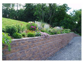
Fig. 26.1. Retaining wall. (Source: https://www.langerlandscapes.com)
In many earth work activities, there is excess soil that needs to be disposed safely. Canal construction, dam and reservoir construction, tunneling to convey water from the reservoir/barrage to the power house; generate considerable excess earth, which needs to be safely disposed off such that they do not fall back into an adjoining stream or river. In hilly terrains particularly, vast expanse of flat ground is not available to thinly spread the excess earth. The dug out earth is to be accommodated over smaller areas. This makes it prone to slide down. To avoid this, retaining walls are invariably constructed.
26.2 Types of Retaining Wall
The various types of retaining wall are given as below:
1. Masonry type 2. Semi-gravity type
3. Cantilever type 4. Counterfort type, and
5. Buttressed wall
Fig 26.2 shows the different types of retaining wall.
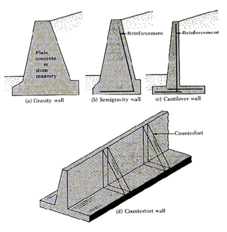
Fig. 26.2. Types of retaining wall. (Source: https://www.concretenetwork.com)
1. Masonry Type
Retaining walls are generally masonry structures. These walls are constructed in between two types of ground surfaces, such as water on one side and land on the other, at different elevations on either side. There may also be soil on both the sides but at different elevations. The material which is supported by the wall is known as the backfill. The surface of the backfill material may be horizontal or inclined. The position of these fill above a horizontal plane, at the top level of the wall is called surcharge, and the angle of inclination of the backfill with the horizontal plane is called the angle of surcharge. Retaining walls constructed to retain water on one side, are also called masonry dams.
Two types of forces act on these types of structures, they are vertical and lateral. The vertical forces are due to self-weight of the structure, and the lateral forces are due to the pressure of wind, earthquake, earth material or water. The masonry structures are designed, such that the shearing action due to the tangential force on the masonry at any level is not greater than the natural friction between any two types of masonry materials. The stability of the structures depends on its self-weight. Therefore, the dimensions of the structures are so designed that the structure remains stable under lateral forces.
The general conditions for the stability of the structure are that there should be no tension across the wall cross section (because, non-reinforced masonry is weak in tension), the maximum compressive stress should be within the limit of safe stress for the material, the shear force should not be greater than the natural friction between the masonry, and the restoring moment should be greater than the overturning moment.
2. Semi-Gravity Type
This type of retaining wall requires a wider toe to increase the base width of the wall, which causes a major role to prevent the development of tension in the retaining wall. In addition, semi-gravity type retaining wall also needs a fairly heavy section of stem. However, by providing the reinforcement in toe and stem, a heavy section of the wall can be reduced in size and made relatively lighter.
3. Cantilever Type
This type of retaining wall consists of a base slab and a vertical slab, which are joined together in a monolith construction. The front portion of the base slab is termed as toe and rear is known as heel. All these components are designed as cantilever. Sometimes to prevent the wall against sliding, a vertical downward projection known as a key is also provided to its base. It increases the resistance of the wall. The position of the key can be fixed at the following points of the base:
(a) Near the toe
(b) Near the heel
(c) Middle of the base
4. Counterfort Type
The cantilever type retaining walls are economical up to the height of 6m only. When the height exceeds 6 m, counterfort type of retaining wall is preferred for construction. The construction of these types of retaining walls can be made more economical by making the stem and heel as a continuous slab over the counterforts. However, to construct this retaining wall additional amounts of concrete reinforcement and framework are required for constructing the counterforts as an additional part of the wall.
5. Buttressed Wall
Buttressed walls are similar in constructional feature to that of counterfort type retaining walls. The only difference is that the buttressed wall has counterforts in front of the wall, while in the other it is not so. Due to this reason, it is named as buttressed wall. In this wall, the projection of the heel is too small. As a result, the backfill contributes very little stability to the wall and therefore, buttressed retaining walls are rarely used.
26.3 Design of Retaining Wall
The wall is predominantly subjected to the following two forces:
(i) Weight of the wall, acting vertically downward
(ii) Horizontal pressure due to earth materials (or water), acting at a distance of one third height of the retaining wall, from the base.
For making the analysis of above two forces, acting on the wall, let the retaining wall has trapezoidal cross section as shown in Fig 26.3, with ‘a’ as the top width, b as the width and H as the height.
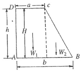
Fig. 26.3. Masonry retaining wall having trapezoidal cross section. (Source: Das, Ghanshyam, 2002)
If soil is filled behind it up to the full height of the wall, (i.e. h=H) then the weight of retaining wall and horizontal pressure due to earth fill are given as follows.
(i) Weight of Retaining Wall
It is given by

Where,
W= weight of the retaining wall (kg/m)
H = height of the wall (m)
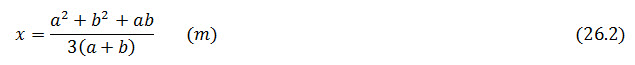
The weight of retaining wall acts at a distance ‘x’ from the vertical face of the wall. The value of ‘x’ computed following the equation
(ii) Horizontal Pressure due to Earth Fill
The distribution of horizontal pressure on retaining wall is similar to that of retaining dam i.e. in triangular form, but in case of retaining wall the maximum pressure exerted by the earth fill is somewhat different. It is given by the following expression:
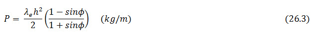 \
\
Where,
P= horizontal pressure acting at a distance h/3 from the base of r, wall (kg/m).
Φ = internal frictional angle of the soil (degree)
Maximum and Minimum Stress
Referring to Fig. 26.4, let R be the resultant force of weight of retaining wall (W) and the horizontal pressure (P), acting at a distance Z from point A.
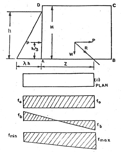
Fig. 26.4. Various forces acting on the retaining wall. (Source: Suresh, 2002)
Now, taking the moment of all forces acting on retaining wall, about A, we have,

The moment of R about point A is zero, because its line of the action passes through point A.
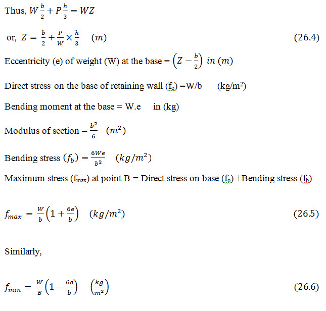
The bending moment of the wall is developed at its base, due to horizontal pressure caused by the earth fill. This tends to shift the line of action of weight (W) of the retaining wall from the center of the base to right side, at a distance Z from the vertical face. In this condition, the eccentricity (e) at the base is equal to. Since maximum stress occurs at point B and minimum at point A, the nature of these stresses will be compressive so long as the values of the stresses are positive. The maximum stress will always be positive, which indicates the stress to be of compressive in nature. The minimum stress may not be always positive, it can be negative also. The negative value of stress indicates to be of tensile in nature. The tensile stress developed in masonry retaining wall, causes failure. It must be avoided. To avoid the possibilities of development of tension in retaining wall, the value of e should always be less than b/6, which can be obtained by equating the equation of minimum stress equals to zero. That is:
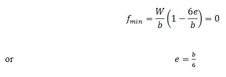
The above equation states that, if the value of e is less than b/6, the fmin will be compressive in nature and when e is equal to b/6, the fmin will be zero. But when the value of e exceeds b/6, then minimum stress is tensile in nature. Thus, to avoid the possibilities of development of tension in masonry retaining wall, the eccentricity should always be less than b/6 or at most it should be equal to b/6.
Last modified: Monday, 23 September 2013, 10:28 AM