Site pages
Current course
Participants
General
Module 1: Formation of Gully and Ravine
Module 2: Hydrological Parameters Related to Soil ...
Module 3: Soil Erosion Processes and Estimation
Module 4: Vegetative and Structural Measures for E...
Keywords
29 March - 4 April
5 April - 11 April
12 April - 18 April
19 April - 25 April
26 April - 2 May
Lesson 27 Culverts
27.1 Introduction
Culvert is a structure constructed to link a pathway and is used to pass flowing water underneath and across a road (as illustrated in Fig. 27.1 and 27.2), a railway line, etc, simultaneously maintaining the movement on the road, the rail or other traffic. Sometimes, a culvert may be constructed to cross over a natural depression. Culverts are made of different materials like steel, polyvinyl chloride, concrete and wood, with a suitable combination of some of them. Concrete comes in many shapes and sizes, including round, elliptical, flat- bottomed, pear shaped, and box. They vary from small drainage culverts on highways and driveways to large diameter structures. Long and wide culverts are known as bridges and they require rigorous construction methods. Very small culverts, as are required for movement of humans and cattle in a farm, may be made with a suitable diameter strong pipe laid at the bottom along the water flow direction. The pipe is covered by earth. However, on such a culvert in a farm, the earth cover is replaced by reinforced concrete slab with a required span and width, erected on piers, if movement of farm machinery is involved.
A culvert is defined as the following:
A structure that is usually designed hydraulically to take advantage of submergence to increase hydraulic capacity.
A structure used to convey surface runoff through embankments.
A structure, as distinguished from bridges, that is usually covered with embankment and is composed of structural material around the entire perimeter, although some are supported on spread footings with the streambed serving as the bottom of the culvert.
A structure that is about 6 meter or less in centerline span width between extreme ends of openings for multiple boxes. However, a structure designed hydraulically as a culvert is treated in this Chapter, regardless of its span.
Some of the basic concepts and definitions that are commonly used in the hydraulic design and installation of culvert are discussed here.
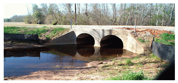
Fig. 27.1. Culverts for stream crossing. (Source: http://water.epa.gov/polwaste/nps/urban/upload/2003_07_24_NPS_unpavedroads_ch3.pdf)
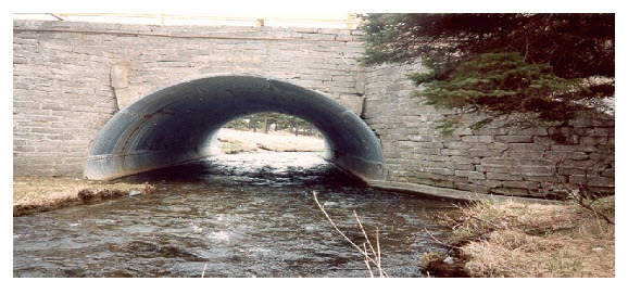
Fig. 27.2. Bridge culvert. (Source: http://www.env.gov.nl.ca/env/waterres/regulations/appforms/chapter5.pdf)
27.2 Types of Culverts
The types of culvert are (as illustrated in Fig. 27.3):
-
Pipe Culvert: Single or Multiple
The Pipe culvert is used for very small drainage works, passing through the embankment of road or railway. It consists of one or more pipes placed side by side. These are made of smooth steel, corrugated metal or concrete materials. The pipe culvert ranges from 30 to 200 cm in diameter and is the cheapest among others. The primary purpose is to pass the water under roads. For the high stream banks round culverts are best suited.
-
Pipe Culvert: Arch Single or Multiple
It is suitable for large waterways and provides low clearance. At low flows it provides greater hydraulic advantage to fishes to move and requires less road fill.
-
Box Culvert: Single or Multiple
Box culverts are preferred for construction, especially in loose soil condition and for a larger span. During brief runoff periods, a box culvert is used to transmit water. It can have artificial floor such as concrete. This provides more room for wildlife than the large pipe culverts. Reinforced concrete is used for box culverts. The design of this culvert is based on the continuous beam theory. It requires a good and strong foundation to avoid uneven sinking and the resulting damage to the culvert.
-
Bridge Culvert
Bridge size culverts are defined as structures that have an equivalent diameter of around 1500 mm or above. This also includes multiple culverts with an equivalent diameter of around 1500 mm or greater.
-
Arch Culvert
The pipe arch culvert is a round culvert reshaped to allow a lower profile while maintaining similar flow characteristics. When installed with a shallow cover, it works very well. Reinforced concrete, corrugated metals or stone masonry are the materials used for the pipe arch culverts.
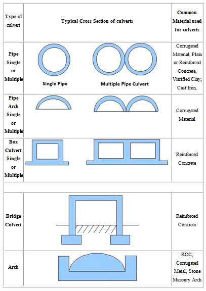
Fig. 27.3. Common Culvert Types. (Source: http://www.aboutcivil.org/culverts-and-its-types.html)
Maintenance of Culvert
Proper maintenance of a culvert is essential for its trouble-free functioning and getting the best performance out of it. A culvert may be damaged and rendered non-functional if loads heavier than that for which the culvert was designed are allowed to pass over; soil erosion at the piers or at the banks, choked water way, etc. To ensure these, the interior of the culvert (i.e., the water way) should be clean always, by removing debris and foreign materials from it. Care and suitable action should be taken such that large vegetation does not grow in the area around culvert, especially on an embankment. Any structural damage, if detected, should be addressed for rectification/repair immediately. As the water flow path dimensions are usually larger at the culvert, farm animals in India are known to gather there not only to drink water but also to dip in the water in summers. This is a common cause of damage to the culverts in agricultural areas and suitable protection mechanism is to be thought and implemented.
27.3 Design of Culverts
27.3.1 Required Design Information
The hydraulic design of a culvert essentially consists of an analysis of the required performance of the culvert to convey flow across the path way. The designer must select a design flood frequency, estimate the design discharge for that frequency, and set an allowable headwater elevation based on the selected design flood and headwater considerations. These criteria are typically dictated by local requirements and certain standards exist in the civil engineering design books on bridges and culverts. The culvert size and type can be selected after the design discharge, controlling design headwater, slope, tailwater, and allowable outlet velocity have been determined.
The design of a culvert includes determination of the following:
Impacts of various culvert sizes and dimensions on upstream and downstream flood risks, including the implications of embankment overtopping.
How will the proposed culvert/embankment fit into the relevant major drainage way master plan, and are there multipurpose objectives that should be satisfied?
Alignment, grade, and length of culvert.
Size, type, end treatment, headwater, and outlet velocity.
Amount and type of cover.
Public safety issues, including the key question of whether or not to include a safety/debris rack
Pipe material.
Type of coating (if required).
Need for fish passage measures, in specialized cases.
Need for protective measures against abrasion and corrosion.
Need for specially designed inlets or outlets.
Structural and geotechnical considerations,
27.3.2 Culvert End Treatments
End structures (as shown in Fig. 27.4) are attached to end of culvert barrel to reduce erosion, inhibit seepage, retain the fill, and improve hydraulic characteristics.
Possible Choices:
Projecting
Mitered
Flared-end Section
Headwalls and Wingwalls
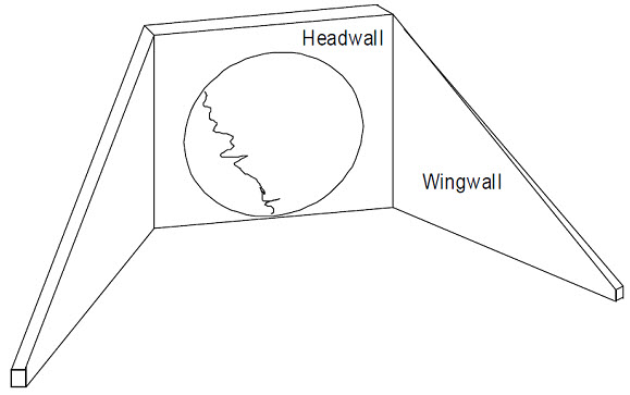
Fig. 27.4. Culvert End Treatments. (Source: https://engineering.purdue.edu/~abe527/lectures/culvertdesign.pdf)
27.3.3 Hydraulic Design Considerations
1. Design Flood Discharge
Watershed characteristics
Design flood frequency or return interval
All designs should be evaluated for flood discharges greater than the design flood
2. Headwater Elevation - check upstream water surface elevation
3. Tailwater - check that outlet will not be submerged
4. Outlet Velocity - usually controlled by barrel slope and roughness
27.3.4 Terminology
(1) Headwater (HW) – Depth from the culvert inlet invert to the energy grade line
(EGL). If the approach velocity head is small then HW is approximately same as the upstream water depth above the invert.
(2) Tailwater (TW) – Depth of water on the downstream side of the culvert. The TW depends on the flow rate and hydraulic conditions downstream of the culvert.
27.3.5 Culvert Design Approaches
1. Design based on design flood discharge and allowable headwater elevation.
Tailwater conditions are to be checked to verify the design.
2. Flood routing through the culvert. Data inputs include
an inflow hydrograph
an elevation versus storage relationship
an elevation versus discharge relationship (rating curve)
27.3.6 Types of Flow Control
1. Inlet Control - flow capacity is controlled at the entrance by the depth of headwater and entrance geometry, including the barrel shape, cross sectional area and the inlet edge.
2. Outlet Control - hydraulic performance controlled by all factors associated with Inlet Control, and additionally include culvert length, roughness and tailwater depth.
27.3.8 Culvert Hydraulics - Inlet Control
Two possible conditions:
(1) Unsubmerged - steep culvert invert and headwater not sufficient to submerge inlet. Culvert inlet acts effectively like a weir. The culvert capacity is given as:
Q = Cw B (HW )3/ 2
Where, B = width of weir crest
A weir coefficient Cw = 3.0 may be assumed for initial calculations.
(2) Submerged - headwater submerges top of culvert inlet but the barrel does not necessarily flow full. Culvert inlet acts like an orifice or sluice gate.
![]()
Where, b = culvert height
HW – b/2 = head on culvert measured from barrel centerline
Orifice discharge coefficient, Cd, varies with head on the culvert, culvert type, and entrance geometry. Nomographs and computer programs are usually used for design. For initial calculations a value Cd = 0.60 may be used.
27.3.9 Culvert Hydraulics - Outlet Control
Outlet control will govern if the headwater is deep enough, the culvert slope is sufficiently flat, and the culvert is sufficiently long.
Three possible flow conditions:
1. Both inlet and outlet submerged, with culvert flowing full.
2. Inlet is submerged but the tailwater does not submerge the outlet. In this case the barrel is full over only part of its length.
3. Neither the headwater nor tailwater depths are sufficient for submergence.
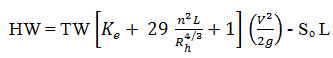
Culvert capacity determined from energy equation:
![]()
Where,
HW - TW = total energy head loss (m)
So = Culvert slop
L = Pipe length
he = entrance head loss (m)
hf = friction losses (m)
hv = velocity head (m)
Entrance Head Loss, he

Culvert Entrance Loss Coefficients, Ke
Pipe with projecting square-edged entrance 0.5
Pipe metered to conform to fill slope 0.7
Box with wing walls at 30o to 75o to barrel 0.4
Friction Losses, hf
Mannings Equation
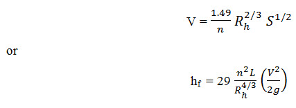
Design equation for Case 1:
Roadway Overtopping
During roadway overtopping, the roadway acts as a weir:
Q = Cw L (HWr )3/2
HWr = upstream depth, measured above roadway crest (m)
27.3.10 Concepts of Culvert Design
Most culverts operate under downstream control. This means that the hydraulic computations proceed from the downstream to the upstream direction.
The design discharge and allowable headwater elevation are initially established. Other constraints such as culvert shape, material, aesthetics, etc. are specified.
Assume a culvert size and check performance assuming both inlet and outlet control. Whichever gives the highest HW elevation controls the hydraulic performance.
Compare culvert performance with design constraints, and select the smallest (least expensive) size that meets the criteria.
Last modified: Monday, 23 September 2013, 10:57 AM