Site pages
Current course
Participants
General
Module 1: Formation of Gully and Ravine
Module 2: Hydrological Parameters Related to Soil ...
Module 3: Soil Erosion Processes and Estimation
Module 4: Vegetative and Structural Measures for E...
Keywords
29 March - 4 April
5 April - 11 April
12 April - 18 April
19 April - 25 April
26 April - 2 May
Lesson 32 Permanent Structures - II
32.1Rubble Masonry Dam
These dams are used in gullies or stream channels with high rates of runoff or where vegetation cannot be established. The construction of this dam is recommended only, where rocks or stones are readily available in nearby areas. The minimum thickness of walls is kept as 30 cm. The downstream slope below the spillway is kept at least 1:2. The thickness of the base should not be less than 3/4th of the height of the dam. As shown in fig. 32.1.
Some details of rubble masonry dams are given as under:
The minimum thickness of side walls cut off walls and apron should be about 30 cm.
The thickness of main wall from the crest of spillway to the top of dam should not be less than 35 cm.
To ensure proper settling, the upstream side of dam should be maintained at an angle of about 10o with the vertical.
The length of apron should not be less than 1.5 times the height of dam, measured from apron floor to the spillway's crest.
For drainage, the provision of drains or weep holes should also be made. They should be located near the base of dam.
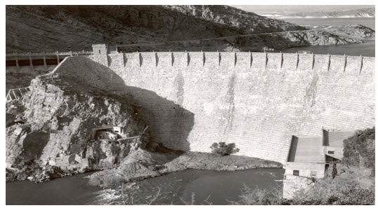
Fig. 31.1. Rubble-masonry gravity arch dam. (Source: http://www.nps.gov/nhl/DOE_dedesignations/Roosevelt.htm)
32.2 Sand Detention Dam
The basic purpose of silt detention dam, as shown in fig. 32.2, is to detain the silt load coming along the runoff from the catchment area into depressed part and simultaneously to harvest water. The location of such dam is decided at the lower reaches of the catchment where water enters the valley and finally made for taking out the water for irrigation purpose. For better result, a series of such dams can be constructed along the slope of catchment.
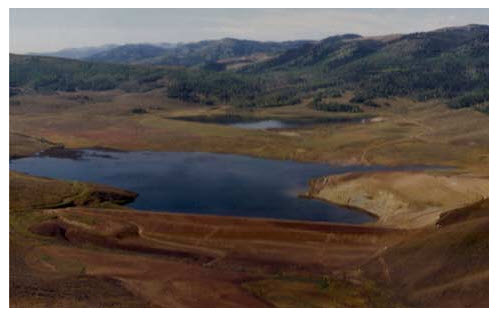
Fig. 31.7. Sand Detention Dam (Smoky canyon dam) (Source: http://www.delhur.com/projectTypes/waterResources.html)
33.3 Rubber Dam
A symbol of sophistication, simple and efficient design, this most recent type of dam uses huge cylindrical shells made of special synthetic rubber and inflated by either compressed air or pressurized water. Rubber dams offer ease of construction, operation and commissioning in tight schedules. These can be deflated when pressure is released and hence, even the crest level can be controlled to some extent. Surplus waters would simply overflow the inflated shell. They need extreme care in design and erection and are limited to small projects. Example of Rubber type: Janjhavathi Rubber Dam (India) as illustrated in fig. 32.3.
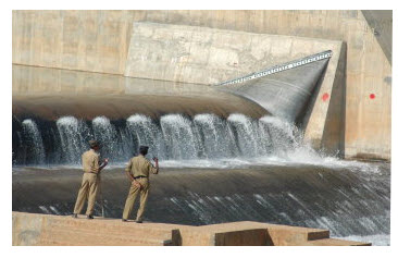
Fig. 31.10. Janjhavathi Rubber Dam (India). (Source: http://www.thehinduimages.com/hindu/photoDetail.do?photoId=6452707)
32.4 Steel Dam
A steel dam, as illustrated in fig. 32.4, consists of a steel framework, with a steel skin plate on its upstream face. Steel dams are generally of two types: (i) Direct-strutted, and (ii) Cantilever type. In direct strutted steel dams, the water pressure is transmitted directly to the foundation through inclined struts. In a cantilever type steel dam, there is a bend supporting the upper part of the deck, which is formed into a cantilever truss. This arrangement introduces a tensile force in the deck girder which can be taken care of by anchoring it into the foundation at the upstream toe. Hovey suggested that tension at the upstream toe may be reduced by flattening the slopes of the lower struts in the bent. However, it would require heavier sections for struts. Another alternative to reduce tension is to frame together the entire bent rigidly so that the moment due to the weight of the water on the lower part of the deck is utilized to offset the moment induced in the cantilever. This arrangement would, however, require bracing and this will increase the cost. These are quite costly and are subjected to corrosion. These dams are almost obsolete. Steel dams are sometimes used as temporary coffer dams during the construction of the permanent one. Steel coffer dams are supplemented with timber or earthfill on the inner side to make them water tight. The area between the coffer dams is dewatered so that the construction may be done in dry for the permanent dam. Examples of Steel Dam: Redridge Steel Dam (USA) and Ashfork-Bainbridge Steel Dam (USA).
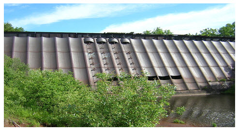
Fig. 31.12. Redridge Steel Dam. (Source:http://commons.wikimedia.org/wiki/File:Redridge_Steel_Dam_UpstreamSide_GateControls_DSCN2191.JPG)
32.5 Diversion Dam
A diversion dam is constructed for the purpose of diverting water of the river into an off-taking canal (or a conduit), as shown in Fig. 32.5, which represent Indian dam. They provide sufficient pressure for pushing water into ditches, canals, or other conveyance systems. Such shorter dams are used for irrigation, and for diversion from a stream to a distant storage reservoir. It is usually of low height and has a small storage reservoir on its upstream. The diversion dam is a sort of storage weir which also diverts water and has a small storage. Sometimes, the terms weirs and diversion dams are used synonymously.
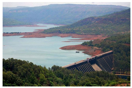
Fig. 31.12. Picture of Koyna Dam in Satara district, Maharashtra. (Source: http://www.thehindu.com/news/national/other-states/irrigation-water-diverted-for-industries-and-domestic-use-in-maharashtra/article4609969.ece)
32.6 Storage Dam
They are constructed to store water during the rainy season when there is a large flow in the river. Many small dams impound the spring runoff for later use in dry summers. Storage dams may also provide water supply, or improved habitat for fish and wildlife. They may store water for hydroelectric power generation, irrigation or for a flood control project. Storage dams are the most common type of dams and in general the dam means a storage dam unless qualified otherwise. One of example shown in fig. 32.6 which is one of the tallest dam in the world.
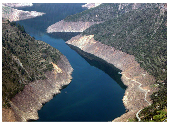
Fig. 31.13. Tehri dam of India. (Source: http://www.indiamike.com/india-images/pictures/tehri-dam)
32.7 Timber Dam
Main load-carrying structural elements of timber dam are made of wood, primarily coniferous varieties such as pine and fir. Timber dams,as presented in fig. 32.7, are made for small heads (2-4 m or, rarely, 4-8 m) and usually have sluices; according to the design of the apron they are divided into pile, crib, pile-crib, and buttressed dams. The openings of timber dams are restricted by abutments. When the sluice is very long, it is divided into several openings by intermediate supports: piers, buttresses, and posts. The openings are covered by wooden shields, usually several in a row one above the other. Simple hoists—permanent or mobile winches—are used to raise and lower the shields.
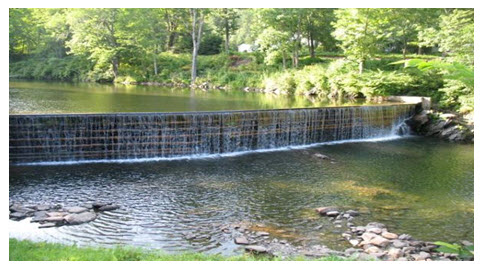
Fig. 31.11. Timber Dam. (Source: http://blog.thecivilengg.com/wpcontent/uploads/2011/09/timber-dam.jpg)
32.8 Earth Dam
An earth dam is made of earth (or soil) built up by compacting successive layers of earth, using the most impervious materials to form a core and placing more permeable substances on the upstream and downstream sides. A facing of crushed stone prevents erosion by wind or rain, and an ample spillway, usually of concrete, protects against catastrophic washout should the water overtop the dam. Earth dam resists the forces exerted upon it mainly due to shear strength of the soil. Although the weight of the structure also helps in resisting the forces, the structural behavior of an earth dam is entirely different from that of a gravity dam. The earth dams are usually built in wide valleys having flat slopes at flanks (abutments).The foundation requirements are less stringent than those of gravity dams, and hence they can be built at the sites where the foundations are less strong. They can be built on all types of foundations. However, the height of the dam will depend upon the strength of the foundation material.
Examples of earthfill dam: The Banasura Sagar dam, which is the largest earthen dam in India and the second largest in Asia, impounds the waters of the Karamanathodu, a tributary of the Kabini river.
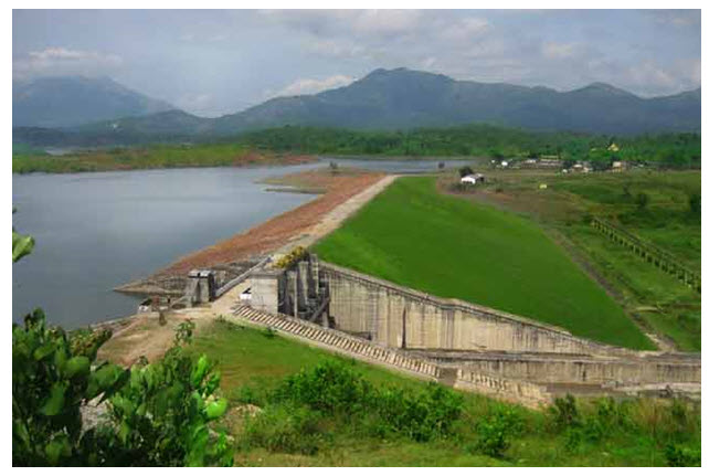
Fig. 32.4. The Banasura Sagar dam. (Source: http://www.banasura.com/banasura-sagar-dam)
32.9 Institutions/Organizations dealing with Soil Conservation Related Issues in India
32.9.1 Central Arid Zone Research Institute, Jodhpur, Rajsthan
India has about 14 per cent of its area under arid climate, 10 percent under hot arid, mostly in Rajasthan and Gujarat states, and 4 percent under cold arid, largely in Jammu and Kashmir state. Because of its harsh environment, agriculture in arid zones is a formidable challenge. Central Arid Zone Research Institute, Jodhpur, a Premier Organization of the Indian Council of Agricultural Research (ICAR), is an autonomous organization under the Department of Agricultural Research and Education, Ministry of Agriculture, Government of India The CAZRI operates through Six Divisions, located at the headquarters in Jodhpur. There are four Regional Research Stations located in different agro-climatic zones to work on location-specific problems. (http://www.cazri.res.in/)
32.9.2 Hazaribagh, Jharkhand
The Soil Conservation Department of Damodar Valley Corporation (DVC), one of the prime river valley projects in the country has been engaged in the task of promoting soil conservation and afforestation in the catchment of the Damodar-Barakar river system for more than five decades now. Four major dams namely, Tilaya, Konar, Maithan and Panchet were constructed between the years 1953 and 1959 with the corresponding catchment areas of 984, 997, 6293 and 10966 km2. The effective reservoir lives of these four dams were estimated as 151, 219, 245 and 97 years, respectively, based on silt observation in the rivers near the dam location. A reservoir sedimentation survey was conducted at Maithon and Panchet, respectively in 1963 and 1962, and the reservoir lives were revised downwards to 98 years and 38 years, respectively due to excessive soil erosion from the catchment areas. The initial soil conservation measures were generally ineffective because the anthropogenic factor was overlooked. The DVC carried out with mainly engineering measures for runoff conservation and sediment control; deforestation of the catchment, overgrazing, unscientific cultivation in the catchment areas continued unabated. Besides, there was a lack of maintenance of the constructed structures. Alerted by the huge reduction in the estimated reservoir lives at Maithon and Panchet, integrated conservation effort was initiated from the mid nineteen sixties and the local community was also involved in this effort. As a result, the reservoir sedimentation survey conducted again in the year 1987 for Maithon and in 1985 for Panchet revealed an estimated increase in the reservoirs to 138 years and 108 years, respectively (Adapted from DVC 1999).
32.9.3 Central Water Commission, Govt. of India
Central Water Commission is a premier Technical Organization of India in the field of Water Resources and is presently functioning as an attached office of the Ministry of Water Resources, Government of India. The Commission is entrusted with the general responsibilities of initiating, coordinating and furthering in consultation of the State Governments concerned, schemes for control, conservation and utilization of water resources throughout the country, for purpose of Flood Control, Irrigation, Navigation, Drinking Water Supply and Water Power Development. It also undertakes the investigations, construction and execution of any such schemes as required. ( http://www.cwc.nic.in/)
Last modified: Tuesday, 24 September 2013, 4:33 AM