Site pages
Current course
Participants
General
Module 1: Formation of Gully and Ravine
Module 2: Hydrological Parameters Related to Soil ...
Module 3: Soil Erosion Processes and Estimation
Module 4: Vegetative and Structural Measures for E...
Keywords
29 March - 4 April
5 April - 11 April
12 April - 18 April
19 April - 25 April
26 April - 2 May
Lesson 30 Control by Permanent Structures
30.1 Spillway
Dams and barrages are constructed to store runoff water from the catchments for its simultaneous and/or subsequent use for hydro power generation, irrigation, drinking water supply, flood control, etc. They are much larger structures constructed across rivers and tributaries than what have been discussed so far as means of gully control measures. Dams and barrages create a reservoir behind them and have a spillway section through which the water in excess of the reservoir capacity is released downstream. The reservoirs need to be protected against uncontrolled sediment deposit in them through erosion control measures adopted in the catchment area. Spillways are also used to flush out some of the sediment deposited in the reservoir. In diversion works, like weirs and barrages, spillways bypass the flow exceeding that which is released into the system like irrigation canals, power canals, feeder canals, link canals etc. Ordinarily, the excess flow is drawn from the top of the pool created by the dam and conveyed downstream through the spillway, back into the same river or to some other drainage Channel. Fig. 30.1 shows spillways in Bhakra dam and Hirakud dam respectively.
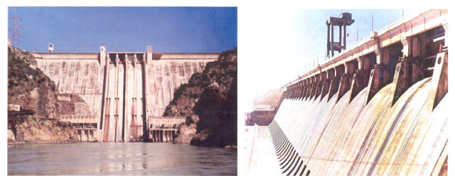
Fig. 30.1. Spillway in bhakra dam and spillway in hirakud dam. (Source: http://profskmazumder.com/IT%20PDF/Ref_02.pdf)
30.2 Components of a Spillway
A spillway generally has the following components
1. Entrance channel
2. Control structure
3. Discharge channel (or waterway)
4. Terminal structure (energy dissipater)
5. Exit channel
However, entrance and exit channels may not be required for some spillways, which one usually comes across in agricultural lands.
1. Entrance Channel
Entrance channels are required in those types of spillways in which the control structure is away from the reservoir. The entrance channel draws water from the reservoir and carries it to the control structure. Entrance channels are not required for spillways which draw water directly from the reservoir.
2. Control Structure
The control structure (also called control) is the most important component of the spillway. It controls the outflow from the reservoir. The control structure is designed such that it does not permit the outflow from the reservoir when the water level is lower than a predetermined level but permits the outflow as soon as the water level rises above that level. Generally the control structure is located at the upstream end of the spillway structure. The control structure usually consists of either an orifice or a weir. In most of the spillways, the control structure is an overflow crest of a weir. The weir may be sharp-crested, board-crested or ogee-shaped.
3. Discharge Channel (or waterway)
The outflow released through the control structure is usually conveyed to the terminal structure through a discharge channel or waterway. Thus the discharge channel conveys the water safely from the control structure to the river downstream. It is also called a conveyance structure. The conveyance structure may have different forms. It is usually the downstream face of an overflow darn for the spillway constructed as an overflow spillway in the body of the dam. It may be in the form of an open channel, a closed conduit placed through or under a dam, or a tunnel excavated through an abutment, depending upon the type of spillway. The discharge channel may have a variety of cross-sections, depending upon the geologic and topographic characteristics of the site and the hydraulic requirements.
4. Terminal Structure (energy dissipater)
When the water flows from the reservoir over the spillway, the static energy is converted into the kinetic energy. This results in very high velocity of flow at the downstream end of the spillway. It may cause serious scour at the downstream end. It may also damage the dam, the spillway and other appurtenant structures. It is, therefore, necessary that the high energy of flow is dissipated before the flow is returned to the river downstream. Terminal structures (or energy dissipaters) are provided at the downstream end of the discharge channel to dissipate the excess energy.
Hydraulic jump basin, a roller bucket, a ski-jump bucket, or some other suitable energy dissipating device is provided for the dissipation of excess energy. Smaller version of such energy dissipaters are also used with check dams and similar small structures.
5. Exit Channel
The exit channels are provided to convey the spillway discharge from the terminal structure to the river downstream. An exit channel is not required for the spillways which discharge water directly into the river downstream.
30.3 Classification of Spillways
The spillways can be classified into different types based on the various criteria, as explained below:
A. Classification Based on Purpose
1. Main (or service) spillway
2. Auxiliary spillway
3. Emergency spillway
B. Classification Based on Control
1. Controlled (or gated) spillway
2. Uncontrolled (or ungated) spillway
C. Classification Based on Prominent Feature
1. Free overfall (or straight drop) spillway
2. Overflow or Ogee spillway
3. Chute (or open channel or trough) spillway
4. Side-channel spillway
5. Shaft (or morning glory) spillway
6. Siphon spillway
30.4 Classification Based on Purpose
a. Main (or service) Spillway
A main (or service) spillway is the spillway designed to pass a prefixed or the design flood. This spillway is necessary for all dams and in most of the dams, it is the only spillway. Therefore, in general terms, the spillway means the main spillway.
b. Auxiliary Spillway
An auxiliary spillway is usually constructed in conjunction with a main spillway. The main spillway is usually designed to pass floods which are likely to occur more frequently. When the floods exceed the designed capacity of the main spillway, the auxiliary spillway comes into operation and the total flood is passed by both the spillways.
c. Emergency Spillway
An emergency spillway is sometimes provided in addition to the main spillway. It comes into operation only during an emergency which may arise at any time during the life of the dam. Thus an emergency spillway is an additional safety valve of the dam. Some of the conditions which may lead to emergency are as follows:
(i) When the actual flood exceeds the design flood.
(ii) When there is an enforced shutdown of the outlets.
(iii) When there is malfunctioning of spillway gates.
(iv) When there is damage or failure of some part of the main spillway.
(v) When a high flood occurs before the previous flood has been evacuated by the main spillway.
The emergency spillway is generally in the form of a fuse plug or a breaching section which is washed out as soon as the water level in the reservoir reaches a predetermined elevation. The breaching section is sometimes called fuse plug spillway.
(i) An auxiliary spillway is designed to discharge a portion of design flood. An auxiliary spillway operates when the flood is less than the design flood but it is more than the capacity of the main spillway; whereas an emergency spillway operates only when the design flood is exceeded.
(ii) An auxiliary spillway may be of any type, but the emergency spillway is usually a fuse plug.
(iii) An auxiliary spillway may also be designed to work as an emergency spillway when the design flood is exceeded. It works as an auxiliary spillway when the flood exceeds the capacity of the main spillway but it is less than the design flood.
30.5 Classification Based on Control
a. Controlled (or gated) Spillway
A controlled spillway is one which is provided with the gates over the crest to control the outflow from the reservoir. In the controlled spillway, the full reservoir level (F.R.L.) of the reservoir usually coincides with the top level of the gates. Thus the water can be stored up to the top level of the gates. The outflow from the reservoir can be varied by lifting the gates to different elevations. It may be noted that in a controlled spillway the water can be released from the reservoir even when the water level is below the full reservoir level. Depending on the flow release requirement, some selected gates may also be opened.
b. Uncontrolled (or ungated) Spillway
The gates are not provided over the crest to control the outflow from the reservoir. The full reservoir level (F.R.L.) is at the crest level of the spillway. The water escapes automatically when the water level rises above the crest level. Thus the main advantage of an uncontrolled spillway is that it does not require the gates, the operator and lifting power of the operator to operate the gates.
30.6 Classification Based on the Pertinent Feature
There are 8 different types of spillways based on the pertinent feature.
(1) Overfall Spillway
A free overfall spillway (or a straight drop spillway) is the one in which the control structure consists of a low-height, narrow-crested weir and the downstream face is vertical or nearly vertical so that the water falls freely more or less vertical. The overflowing water may discharge as a free nappe, as in the case of a sharp-crested weir, or it may be supported along the narrow section of the crest.
Sometimes, the crest of the spillway is extended in the form of an overhanging lip for directing the discharge away from the downstream face. In all cases, the nappe is properly ventilated to prevent pulsating and fluctuating jets. If the tail water depth is adequate, a hydraulic jump may be formed after the jet falls from the crest, which can be used for the dissipation of energy. However, a long flat apron would be required to contain the hydraulic jump. Moreover, the floor blocks and an end sill may also be required for the establishment of the jump. A free overfall spillway is commonly used for a low arch dam whose downstream face is almost vertical. This type of spillway is also used as a separate structure for low earth dams. The design of a free overfall spillway is similar to that of a vertical drop weir. Fig. 30.2 shows the function of overfall spillway.
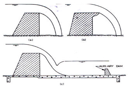
Fig. 30.2. Free overfall spillway. (Source: http://www.most.gov.mm/techuni/media/CE_05016_ch1.pdf)
(2) Ogee - Shaped (or Overflow) Spillway
An overflow spillway, as presented in fig. 30.3, can be gated or ungated, and it normally provides for flow over a gravity dam section. The flow remains in contact with the spillways surface (except for possible aeration ramps) from the crest of the dam to the vicinity of its base. The ogee or overflow spillway is the most common type of spillway. It has a control weir that is ogee or S-shaped. It is a gravity structure requiring sound foundation and is preferably located in the main river channel, although there are many spillways located on the flanks in excavated channels due to foundation problems.
The structure divides naturally into three zones:
(a) The crest,
(b) The Rear Slope
(c) The Spillway Toe
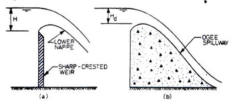
Fig. 30.3. Ogee - Shaped (or Overflow) Spillway. (Source: http://www.most.gov.mm/techuni/media/CE_05016_ch1.pdf)
3. Chute (or open channel or trough) spillway
A discharge channel downstream of the control structure, known as a chute, as shown in fig. 30.4, may be straight or curved with sides parallel, converging, or diverging. It may be either rectangular or trapezoidal in cross-section and may have either a constant or a variable bottom width. Discharge channel dimensions are governed primarily by hydraulic requirements but the selection of profile, cross-sectional shape, width, and length is influenced by geological and topographical features at the site. Open channels excavated in the abutment usually follow the ground surface profile.
For earth dams and rockfill dams, a separate spillway is generally constructed in a flank or a saddle away from the dam if a suitable site exists. Sometimes, even for a gravity dam, a separate spillway is required when the valley is narrow and an overflow spillway cannot be provided at the dam site. The chute spillway is generally most suitable for such conditions.
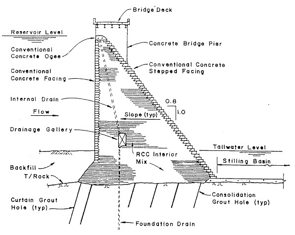
Fig. 30.4. Chute spillway. (Source: http://www.media.rmutt.ac.th/media/e-Book/Engineer/Hydraulic%20and%20Pneumatic/Hydraulic%20Design%20Handbook/0071449590_ar017.pdf )
4. Side-Channel Spillway
A side-channel spillway can be gated or ungated and provides for flow into a chute or tunnel at right angles because the abutment topography is not favorable for a normal crest alignment. A side channel spillway combines an overfall section with a channel parallel to it, which carries the spillway discharge away to a chute or a tunnel. The analysis of flow in a side channel spillway has undergone gradual refinement over the years. The simplest form of analysis is based on the law of conservation of linear momentum, assuming that the only force producing motion in the channel results from the fall of water surface in the direction of spillway axis. The energy of the flow falling down the crest is assumed to be dissipated through it intermingling with the channel flow and offers no assistance in moving the water. Fig. 30.5 shows the arrangement of typical of a side- channel spillway.
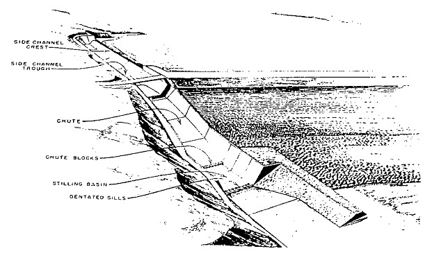
Fig. 30.5. Typical arrangement of a side-channel spillway. (Source: http://www.media.rmutt.ac.th/media/e-Book/Engineer/Hydraulic%20and%20Pneumatic/Hydraulic%20Design%20Handbook/0071449590_ar017.pdf)
5. Shaft (or Morning Glory) Spillway
A shaft (or morning glory) spillway consists of a large vertical funnel, with its top surface at the crest level of the spillway and its lower end connected to a vertical (or nearly vertical) shaft. The other end of the vertical shaft is connected to a horizontal (or nearly horizontal) conduit or tunnel, which extends through or round the dam and carries the water to the river downstream (Fig. 30.6). When the water level rises above the crest level, it starts overflowing the crest and drops from the rim of the funnel into the vertical shaft and then flows in the horizontal conduit, which conveys it past the dam. The transition between the shaft and the horizontal conduit should be smooth to avoid cavitation. A shaft spillway is used at the sites where the conditions are not favorable for an overflow spillway or a chute spillway. It is generally considered undesirable to construct a spillway just adjacent to an earth dam. Therefore, an overflow spillway is ruled out if there is not an adequate space. If the topography of the site is also such that a chute spillway cannot be constructed, a shaft spillway may be considered as an alternative to a side channel spillway.
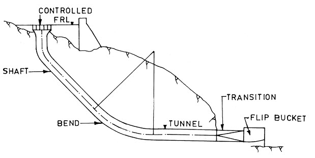
Fig. 30.6. Shaft (or Morning Glory) Spillway. (Source: Khatsuria, R. M., 2005)
6. Siphon Spillway
The discharge over an overflow spillway is a function of the head measured over its crest. Enclosing the crest and making the resulting conduit flow full can substantially increase this effective head. The head on the spillway is then the difference in elevation between the reservoir surface and the spillway outlet. However, the flow near the crest of the spillway would then be under a negative pressure. In other words, the conduit becomes a siphon. All necessary precautions must be taken to ensure that the vacuum is maintained and that it does not become so excessive as to cause cavitation. Typical standard siphon spillway shown in fig. 30.7.
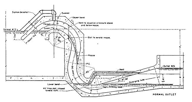
Fig. 30.7. Typical standard siphon spillway. (USBR, 1987). (Source: http://www.media.rmutt.ac.th/media/e-Book/Engineer/Hydraulic%20and%20Pneumatic/Hydraulic%20Design%20Handbook/0071449590_ar017.pdf)
7. Conduit (or Tunnel) Spillway
Tunnel spillways, as shown in fig. 30.8, are used with embankment dams, where there is no suitable location for a chute spillway. A competent rock abutment is required. Tunnel spillways can be gated or ungated, depending on topographic and geologic constraints at the tunnel entrance. In some cases, gates may be required. A tunnel spillway generally consists of the following elements:
entrance structure,
inclined tunnel section,
flat tunnel section, and
flip-bucket.
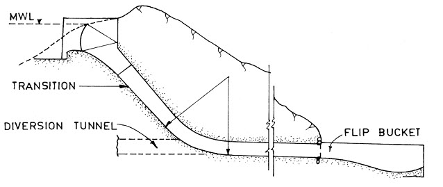
Fig. 30.8. Typical Tunnel spillway. (Source: Khatsuria, R. M., 2005)
8. Orifice Spillway
An orifice spillway is normally gated and is used when substantial discharge capacity is needed at low reservoir levels, as illustrated in Fig. 30.10. For instance, it is useful when sediment sluicing is required. It also is useful for diverting flow during construction. Gate sizes are normally smaller for these spillways, but higher head and sealing details can make them expensive. Typical arrangement of an orifice spillway shown in fig. 30.10.
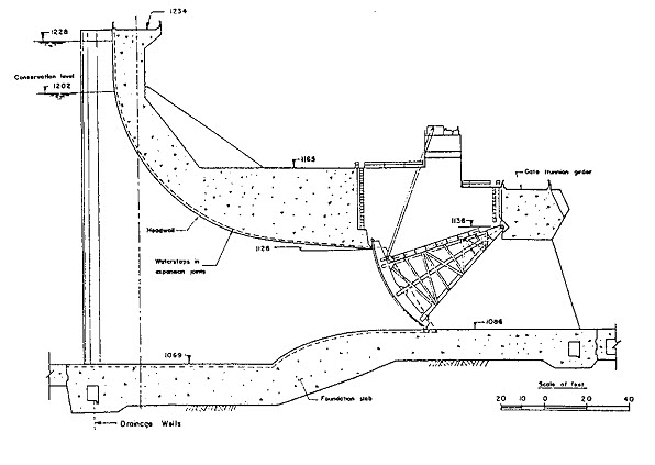
Fig. 30.10. Typical arrangement of an orifice spillway control structure. (Source: http://www.media.rmutt.ac.th/media/e-Book/Engineer/Hydraulic%20and%20Pneumatic/Hydraulic%20Design%20Handbook/0071449590_ar017.pdf)
Last modified: Monday, 23 September 2013, 11:43 AM