Site pages
Current course
Participants
General
MODULE 1.
MODULE 2.
MODULE 3.
MODULE 4.
MODULE 5.
MODULE 6.
MODULE 7.
MODULE 8.
MODULE 9.
MODULE 10.
LESSON 3. DESIGN FOR STATIC LOADING
3.1 Load & Its Determination
All the machine members are subjected to different types of loads that may be acting because of energy, torque or power transmission, their self weight, frictional resistance, inertia or centrifugal forces or due to temperature gradient. Load may be classified as static or dynamic.
Static load is the load which does not change in magnitude or direction and gradually increases to a steady value e.g. dead weight of machine elements. Dynamic load is the load which changes in magnitude or direction or both with respect to time e.g. load acting on the connecting rod of an internal combustion engine. Impact load (load applied with certain velocity) and shock load (suddenly applied load) are also types of dynamic load.
Determination of appropriate loads acting on a machine member is a critical and challenging task. All the stress and deflection analysis is useless and the component cannot function satisfactorily if the operating loads are not calculated or predicted correctly. Sometimes the operating loads are easily determinable e.g. load on a shaft running at known speed and transmitting a known value of torque. But often the loads are difficult to determine e.g. the load on vehicle chassis which depends on road condition and driving practices. Loads acting on a machine member may be directly known or may have to be calculated using basic concepts of engineering mechanics etc. Sometimes experimental methods are used to obtain a statistical definition of the load. Also sometimes the service loads are estimated with the help of record of service failures and strength analysis. After the determination or estimation of applied load, load acting on different members of the machine are determined with the help of free body diagrams and basic equilibrium equations of forces and moments.
3.2 Failure Criteria
A machine element is said to have failed when it ceases to perform its intended function. It may happen if its stress or deflection crosses the acceptable limit. Excessive deformation of a particular element may lead to unwanted interference between the machine elements or jamming of the machine and therefore deformation is considered as a failure criterion. Same way, excessive stresses may result in yielding or fracture of a machine element making it unable to perform its desired function. When stress developed in a ductile material reaches the yield strength, it starts yielding and excessive plastic deformation occurs, therefore Yield strength is taken as failure criterion for ductile materials. In brittle material, very small plastic deformation occurs and fracture takes place once the stress developed reaches Ultimate Tensile Strength. Therefore Ultimate Tensile Strength is considered as failure criterion for brittle materials. Bearing Pressure (for components rubbing against each other with appreciable relative velocity e.g. bearings, clutches, brakes etc.) and wear (for components having sliding or rolling motion e.g. gears, bearings, bushes, piston-cylinders etc.) are examples of other failure criteria.
3.3 Factor of Safety & Allowable Stresses
The factor of safety is a measure of reserve strength provided to take care of any unexpected or unpredicted conditions that may arise due to uncertainties in the properties of the material, magnitude & direction of the load and operating conditions. Value of factor of safety thus depends upon effect of failure (level of severity, cost & danger involved) , type of load (static or dynamic), accuracy in load calculations, material selected (ductile, brittle, homogeneity), desired reliability, service conditions (normal, corrosive, temperature level), manufacturing quality (variation in desired dimensions, quality) and cost etc. Depending upon the criteria of failure decided, strength of the material is divided by factor of safety to obtain allowable stress or design stress which is then used to determine the dimensions of the components as discussed in the next article.
Allowable stress,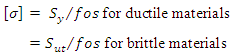
where, \[{S_y}\] is yield strength, \[{S_{ut}}\] is ultimate tensile strength and \[fos\] is factor of safety.
3.4 Design for Simple Stresses
When a mechanical component is subjected to an external load, a resisting force is set up within the component. This resisting force per unit area of the component is called stress. The maximum stress developed in a member should not exceed the allowable value as obtained from the material strength considering certain value of factor of safety i.e any stress ‘σ ’ should always be ≤ [σ ] . Limiting values of dimensions desired can be calculated by equating σ and [σ ]. Equation σ = [σ ] is called design equation and its use for simple stresses is discussed here.
3.4.1 Direct Tensile & Compressive Stress
When the fibers of the component tend to elongate under the external load, stress developed in the component is called tensile stress. On the other hand, when the fibers tend to shorten under the external load, stress developed in the component is called compressive stress.
![]()
where, P is external load, A is cross-sectional area of the component and [σ] and [σc] are allowable tensile and compressive stress of the material. From P / A = [σ] or P/A = [σc], minimum cross-sectional area required to withstand a known load, P can be determined for given allowable stresses.
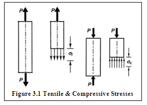
Figure 3.1 shows tensile and compressive stress developed in members subjected to load P.
Tensile or compressive strain is the deformation per unit length and is given by,
![]()
According to Hook's Law, within the elastic limit, stress is directly proportional to strain. Therefore, σt ∞ ε or σt = Eε
where, constant of proportionality E is known as Young’s Modulus or Modulus of Elasticity.
E = 207000 N/mm2 for Carbon Steels, 100000 N/mm2 for Grey Cast Iron
3.4.2 Direct Shear Stress
When the external load acting on the component tends to slide the adjacent planes with respect to each other, the resulting stresses on these planes are called direct shear stresses.
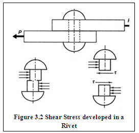
Figure 3.2 shows two plates joined together with the help of a rivet and subjected to load P. In this case the rivet is subjected to direct shear stress. Average shear stress is given by,
![]()
where, P is external load, A is cross-sectional area of the component and \[\left[ \tau\right]\] is allowable shear stress.
Shear strain is defined as the change in right angle of a shear element.
Within the elastic limit, \[\tau= G\gamma\] , where, \[\gamma \] is Shear Strain and G is Modulus of Rigidity
G = 80000 N/mm2 for Carbon Steels, 40000 N/mm2 for Grey Cast Iron.
The relation between modulus of elasticity, modulus of rigidity and poisson's ratio (μ) is given by, \[E = 2G\left( {1 + \mu } \right)\]
3.4.3 Bending Stress
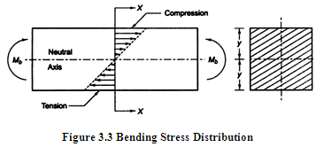
When a machine member is subjected to bending moment, tensile stress develops on one side of the neutral axis and compressive stress on the other. Therefore, the outside fibers are in tension and the inside fibers are in compression. The bending stress at any fiber is given by,
![]()
where, M is Applied bending moment, I is Moment of inertia of the cross-section about the neutral axis and y is the distance of the fiber from the neutral axis. Distribution of bending stress is linear as shown in Figure 3.3. Stress is proportional to the distance of the fiber from neutral axis and is maximum in the farthest fiber.
3.4.4 Torsional Shear Stress
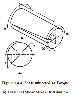
Figure 3.4a shows a shaft subjected to torque. Stress induced in a machine member to resist the action of twist is called torsional shear stress. It is given by, ![]() where, T is applied torque, r is radial distance of the fibre from the axis of rotation and J is Polar moment of inertia of the shaft about the axis of rotation. Distribution of torsional shear stress is shown in Figure 3.4b. Stress is maximum at the outer fiber and zero at the axis of rotation. Angle of twist for a given value of applied torque, T and length of shaft, l can be calculated using the relation, \[T/J = G\theta /l\] , where, \[\theta \] is angle of twist (radians) and G is Modulus of rigidity.
where, T is applied torque, r is radial distance of the fibre from the axis of rotation and J is Polar moment of inertia of the shaft about the axis of rotation. Distribution of torsional shear stress is shown in Figure 3.4b. Stress is maximum at the outer fiber and zero at the axis of rotation. Angle of twist for a given value of applied torque, T and length of shaft, l can be calculated using the relation, \[T/J = G\theta /l\] , where, \[\theta \] is angle of twist (radians) and G is Modulus of rigidity.
3.4.5 Bearing or Crushing Stress
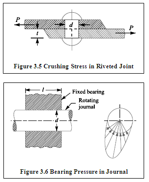
Crushing means to press or squeeze with a force that destroys or deforms or to squeeze into small fragments. Crushing or Bearing stress is defined as the compressive stress developed at the surface of contact between two interacting members that are relatively at rest. Crushing stress is assumed to act uniformly on the projected area. Consider a riveted joint as shown in figure 3.5. If d is diameter of the rivet and tis thickness of the plate, crushing stress is given
by, ![]()
If n is the total number of rivets used, total projected area will become n.d.t.
Also, the local compression that exists at the surface of contact between two members that are in relative motion is called bearing pressure. For example, bearing pressure exists between the contact surfaces of a journal rotating in a fixed bearing as shown in figure 3.6. For a journal of diameter, d and contact length, l, bearing pressure is given by,
![]()
3.4.6 Thermal Stresses
Materials expand with increase in temperature and contract with decrease in the temperature. Stresses develop in a component, if it is prevented from freely expanding or contracting under the effect of temperature change. Theses stresses are called thermal stresses. Change in length of any machine member as a result of temperature change is given by, \[\delta l = l\alpha t\]
where, l is original length of the member, a is Coefficient of thermal expansion and t is rise or fall of temperature. If this change in length is prevented i.e. the member is not allowed to freely expand or contract, strain induced in the body is given by,
![]()
where, E = Modulus of Elasticity of material of the member
References
-
Design of Machine Elements by VB Bhandari
-
Mechanical Engineering Design by J.E. Shigley
-
Analysis and Design of Machine Elements by V.K. Jadon
-
Machine Design by S.G. Kulkarni
-
Machine Elements in Mechanical Design by Robert L. Mott
Last modified: Wednesday, 19 March 2014, 5:33 AM