Site pages
Current course
Participants
General
MODULE 1.
MODULE 2.
MODULE 3.
MODULE 4.
MODULE 5.
MODULE 6.
MODULE 7.
MODULE 8.
MODULE 9.
MODULE 10.
LESSON 5. STRESS CONCENTRATION AND CREEP
5.1 Stress Concentration
The basic stress equations for tension, compression, bending, and torsion are based on a number of assumptions. One of the assumptions is that there are no geometric irregularities or abrupt change in the cross-section of the member. But these irregularities and changes in the cross-section of members are unavoidable. There will be holes, oil grooves, notches, keyways, splines, screw threads etc.

Figure 5.1 Stress Concentration
Any of the discontinuities in a machine part alters the distribution of stress in its vicinity and localized stress much higher than those calculated with the elementary stress equations are observed. This localization of high stresses due to geometrical irregularities or abrupt changes of the cross-section is called ‘stress concentration’ and the discontinuities are called stress raisers. Stress concentrations can also arise from some irregularity. Stress distribution in a plate with a small circular hole, subjected to tensile load, is shown in figure 5.1. In addition to the abrupt changes in the cross-section, other causes of stress concentration can be variation in material properties e.g. internal cracks, flaws, air holes, foreign inclusions etc. and surface irregularities like scratches or stamp marks.
To consider the effect of stress concentration, stress concentration factor is used, which is the ratio of maximum stress to nominal stress.
Stress concentration factor for normal stress, Stress concentration factor for shear stress,


Where, σmax , \[{\tau _{max}}\] = localized stresses near the discontinuities
σ0, \[{\tau _0}\] = Nominal stresses as determined by elementary equations for minimum cross-section
For the plate shown in figure 5.1, if ‘w’ and ‘t’ are width and thickness of the plate, ‘d’ is diameter of the hole and ‘P’ is the applied load, nominal tensile stress is given by,
Value of stress-concentration factor depends on the geometry of the part only and is independent of the material used. For this reason, it is called theoretical or geometric stress-concentration factor. Stress-concentration factors for different geometric shapes are found by using experimental techniques like photo-elasticity, grid methods, brittle-coating methods, and electrical strain-gauge methods. The finite-element method has also been used. Theoretical stress concentration factors for different configurations are available in handbooks, few of which are shown in figures below [charts for stress concentration factors are to be provided here].
5.2 Methods to Reduce Stress Concentration
Effect of stress concentration cannot be completely eliminated but its effect can be reduced by slightly altering the geometry of the components. Flow analogy is helpful in understanding how a particular discontinuity affects the stress distribution around it and how its effect can be reduced. Figure 5.2 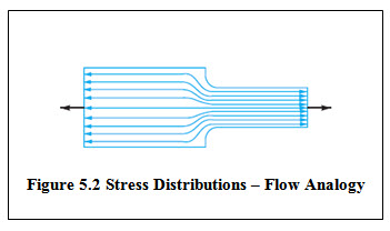 shows the stress distribution in an axially loaded plate which is similar to the velocity distribution in fluid flow in a channel. For a channel having uniform cross-section, velocities are uniform and streamlines are equally spaced. If the cross-section of the channel is suddenly reduced, velocity increases to maintain same flow and the stream lines become narrower. Similarly, with reduction in cross-section, to transmit same force, the stress lines come closer. Location where the cross-section changes, stress lines bend as the stream lines do. Sudden change in the cross-section leads to very sharp bending of stress lines which results in stress concentration. Therefore by avoiding severe bending of the stress lines, effect of stress concentration can be reduced.Figure 5.3 shows certain methods to reduce stress concentration.


Figure 5.3 Methods to Reduce Stress Concentration
5.3 Effect of Ductility & Brittleness on Stress Concentration
Stress concentration has negligible effect on the ductile materials subjected to static loads. Under the static load, when the stress near the discontinuity reaches the yield point, local plastic deformation takes place and the stresses get redistributed, relieving the stress concentration. Therefore, ductile materials, subjected to static loads, are not affected by stress concentration and there is no need to apply stress concentration factor to statically loaded ductile materials.
But for the ductile materials, subjected to dynamic load, stress at the discontinuity may reach its endurance limit leading to fatigue failure. Therefore, stress concentration reduces the endurance limit of ductile materials and stress concentration factor must be used for dynamically loaded ductile materials. This aspect will be discussed in the next lesson.
Stress concentration has more severe effect on the brittle materials due to their inability to plastically deform. As there is no local yielding, stresses don’t get redistributed and local stress due to discontinuity increases highly. Therefore, stress concentration factor must be used for components made of brittle materials subjected to static or dynamic loads.
5.4 Creep
When components are subjected to constant loads continuously for a longer period, they may undergo progressive elastic deformation over time. This time-dependent strain is called creep. Creep can be defined as slow and progressive deformation of material with time under constant stress. Creep deformation is a function of stress and temperature. It generally occurs at absolute temperatures above half the melting point of the material and is even present at room temperature for materials like aluminium, copper and some plastics. Creep increases with the increase in temperature, and therefore becomes very important for components operating at higher temperatures like those of furnaces, steam & gas turbines, internal combustion engines, nuclear reactors, rocket engines etc. The stress can be tensile, compressive, bending or shear.
Components operating at higher temperatures must be designed in such a way that deformation due to creep remains within the allowable limit and also creep deformation doesn’t lead to rupture so that the product performs satisfactorily over time. Creep strength and creep rupture strength are the two important properties of the material related to creep design.
Creep Strength is the maximum stress that the material can withstand for a specified length of time without excessive deformation. Creep Rupture Strength is the maximum stress that the material can withstand for a specified length of time without rupture.
Figure 5.4 shows a typical strain vs time plot known as creep curve. To obtain creep curve, specimen is loaded with a constant force and variation of its length is observed at a constant elevated temperature. Units of strain are mm/mm and time is measured in hours. When the load is applied in the beginning of the test, some instantaneous elastic deformation or initial strain occurs. Then with the passage of time, creep strain occurs. Creep curve is divided into three stages, primary, secondary and tertiary creep, after which the rupture takes place. In the start, strain increases rapidly, known as primary. In the secondary creep, strain increases slowly at a constant rate. Again during the tertiary stage, strain rate increases and necking of the specimen takes place followed by rupture. The creep test is repeated over a range of temperatures to obtain a number of creep curves that are useful for design.

Figure 5.4 Creep Curve
References
-
Design of Machine Elements by VB Bhandari
-
Mechanical Engineering Design by J.E. Shigley
-
Analysis and Design of Machine Elements by V.K. Jadon
-
Machine Elements in Mechanical Design by Robert L. Mott
Last modified: Wednesday, 19 March 2014, 6:33 AM