Site pages
Current course
Participants
General
Module 1_Fundamentals of GW
Module 2_Well Hydraulics
Module 3_Design, Installation and Maintenance of W...
Module 4_Groundwater Assessment and Management
Module 5_Principle, Design and Operation of Pumps
Module 6_Performance Characteristics, Selection an...
Keywords
Lesson 8 Introduction to Water Wells
8.1Introduction
Water well is a hole or shaft, usually vertical, excavated into the earth for bringing groundwater to the surface (Todd, 1980). Wells also serve other purposes such as for observation/exploration, artificial recharge and disposal of wastewaters (very restricted these days due to environmental concern). Wells of horizontal extent (known as ‘horizontal wells’) are sometimes constructed because of special groundwater situations. Horizontal wells are advantageous in the situation where groundwater is to be derived primarily from infiltration of streamflow (e.g., collector wells) or in the situations where aquifers are thin, poorly permeable or underlain by permafrost or saline water (e.g., infiltration galleries, and small-diameter perforated pipes drilled into hillsides). Interested readers are referred to Todd (1980), Raghunath (2007), Michael et al. (2008) and Sarma (2009) for the details about different types of horizontal wells.
This lesson deal with various functions of wells, classification of water wells, advantages and disadvantages of open wells and tubewells/borewells, and the selection of sites for well drilling and type of well.
8.2 Functions of Wells
Wells are used for a variety of purposes, which are as follows:
(1) To supply water to meet domestic, municipal, industrial and agricultural requirements.
(2) To control seawater intrusion.
(3) To remove contaminated water from a polluted aquifer.
(4) To lower water table for construction projects.
(5) To relieve pressure under dams.
(6) To drain agricultural land or urban land.
(7) To inject surface water or once used groundwater into the ground for augmenting groundwater resources. That is, to artificially recharge aquifers at rates greater than the natural recharge.
(8) To dispose of wastewater or hazardous wastes into isolated aquifers. This function of wells is highly restricted these days due to its detrimental effects on environment.
8.3 Classification of Water Wells
There are many ways to classify water wells such as based on well depth, method of construction, type of aquifer, entry of water into wells, type of formation (unconsolidated and consolidated formations), etc. (Sarma, 2009; Michael et al., 2008). In this lesson, the classification which is somewhat generic and has greater practical significance has been adopted. Broadly, water wells can be classified into four groups according to their functions: (a) water supply wells, (b) recharge wells, (c) drainage wells, and (d) monitoring wells. Water supply, recharge and drainage wells can be further classified as open wells and tubewells depending their design and method of construction. Tubewells are classified as shallow tubewells and deep tubewells depending on the availability of aquifer layers and the quantity of desired water supply. Some special types of tubewells are known as borewells and cavity wells. Similarly, a special type of open well is known as a dug-cum-bore well. On the other hand, monitoring wells or observation wells are small-diameter (usually 1” to 2”) tubewells for monitoring groundwater levels and taking groundwater samples for exploring water quality. The major types of water wells are succinctly described in subsequent sections. More detailed discussion on the types of water wells can be found in Sarma (2009) and Michael et al. (2008).
8.3.1 Open Wells
Open wells, also known as dug wells, are popular since ancient times and are the most convenient and cost-effective way of harnessing groundwater present in shallow and low-yielding unconfined aquifers for small-scale water supply (e.g., domestic and small-scale irrigation purposes). They can be constructed both in consolidated formations (e.g., alluvial plains and river deltas) and in unconsolidated formations (e.g., weathered and fractured hard-rock formations). Open wells may be either circular or rectangular in shape. Generally, the circular shape is adopted for open wells in alluvial and other such formations because of its greater structural strength. Open wells are of large size with the diameter usually ranging from 2 to 5 m (Michael et al., 2008), though the diameter may be as large as 20 m (Sarma, 2009) under special circumstances. The open wells of larger size and rectangular in shape are preferred in hard-rock formations to facilitate larger amount of groundwater inflow into the well. The depth of open wells varies from a few meters to about 50 m (Sarma, 2009).
Open wells can be of four types (Michael et al., 2008): (a) unlined open wells, (b) open wells with pervious lining, (c) open wells with impervious lining, and (d) dug-cum-bore wells. They are briefly described in subsequent sub-sections.
8.3.1.1 Unlined and Lined Open Wells
Open wells dug for purely temporary purposes are normally not protected by lining of their walls (Fig. 8.1). The depth of unlined open wells is limited to about 6.5 m in order to ensure stability. However, open wells dug for permanent purposes in loose and unconsolidated formations require lining (steining) to prevent the collapse of side walls and are usually lined with dry bricks or stone masonry (Fig. 8.1). Pervious lining is suitable when the water-bearing formation consists of coarse sand and/or gravel. It is economical and more lasting where aquifer and subsoil conditions are favorable and when the rate of withdrawal is not excessive (Michael et al., 2008).
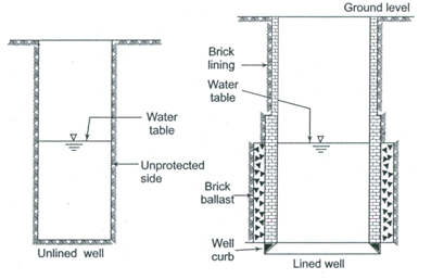
Fig. 8.1. Unlined open well and an open well lined with pervious lining.
(Source: Michael et al., 2008)
Impervious lining such as permanent masonry lining (laid in cement mortar) are normally used in the open wells constructed in alluvial formations (Fig. 8.2). The depth of open wells with impervious linings is generally larger than the two types described above, but the depth usually does not exceed 30 m because of excessive construction cost beyond the 30-m depth. Open wells with reinforced cement concrete (RCC) lining are also sometimes used, especially for greater depths. RCC collar wells (also called ‘ring wells’) are used in some shallow water-table regions mainly for domestic water supply.
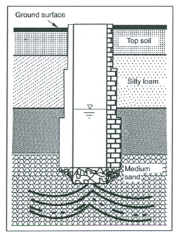
Fig. 8.2. Open well lined with permanent masonry lining.
(Source: Michael et al., 2008)
On the other hand, the open wells in hard-rock areas are excavated pits through the rock and are lined only a couple of meters from top (Fig. 8.3) because the rocky formation ensures the stability of side walls.
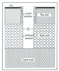
Fig. 8.3. Open well in a hard-rock formation. (Source: Michael et al., 2008)
8.3.1.2 Dug-cum-Bore Wells
Sometimes dug wells are provided with a vertical borehole to augment their yields; such open wells are called Dug-cum-bore wells (Fig. 8.4). The small borehole of size ranging from 4 to 15 cm in diameter is drilled through the bottom of the dug well up to the water-bearing formation lying below the well-bottom. Usually, only one bore is drilled at the center of the dug well constructed in unconsolidated formations. However, in hard-rock formations, the number of bores may range from 1 to 6 depending on the nature of the rock and the size of the dug well (Michael et al., 2008; Sarma, 2009). The vertical bore is provided with a strainer/screen against the aquifer layer and with blind pipes against the non-aquifer layers (Fig. 8.4). Note that dug-cum-bore wells are hydraulically superior to ordinary dug wells and provide higher yields compared to ordinary dug wells. However, their success depends on the availability of a good confined aquifer at a reasonable depth below the bottom of the dug well.
The details about the type of open wells and their design, construction, hydraulics and maintenance can be found in Michael et al. (2008) and Sarma (2009).
8.3.2 Tubewells
Tubewells are wells consisting of pipes ranging in size from 6 to 45 cm in diameter and sunk into an aquifer (Sarma, 2009). Tubewells are constructed by installing a pipe below the ground surface passing through different geological formations comprising water-bearing and non-water-bearing strata. Blind pipes (casing pipes) are placed in the non-water-bearing layers and well screens are placed in the water-bearing layers (Fig. 8.5). Several tubewells have been and are being installed worldwide for meeting water demands in domestic, agricultural and industrial sectors. The type of tubewell to be constructed
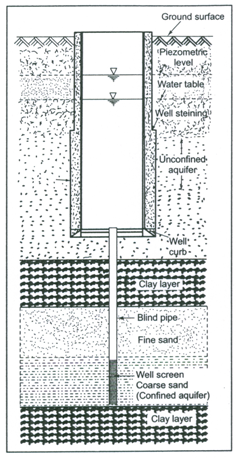
Fig. 8.4. Dug-cum-bore well with a screened vertical bore.
(Source: Michael et al., 2008)
depends on the type of geological formation, intended use of the well and the availability of fund. The design of tubewells is discussed in Lesson 16, while their construction, development and maintenance are discussed in Lessons 17 to 19.
Tubewells are also classified based on the depth, method of construction, entry of water into the wells and the type/nature of the aquifer (Michael et al., 2008; Sarma, 2009). As mentioned above, based on the depth of the well, tubewells
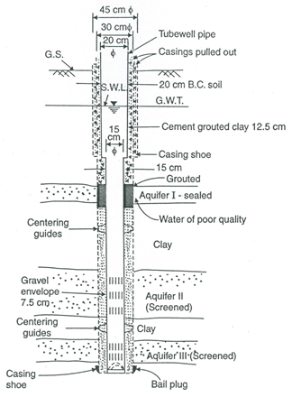
Fig. 8.5. A typical tubewell in an unconsolidated formation.
(Source: Raghunath, 2007)
are classified as shallow tubewells or deep tubewells. Shallow tubewells are of low capacity and their average depth is normally less than 35 m. They mostly tap one aquifer. Deep tubewells are of high capacity and their depth usually ranges from 60 to 300 m (Michael et al., 2008). They often tap two or more aquifers. Based on the method of construction, tubewells are classified as bored tubewells, drilled tubewells, driven tubewells and jetted tubewells; they are described in Lesson 17. Tubewells in unconsolidated formations generally consist of blind pipes, strainers and gravel pack (if necessary). However, tubewells in hard-rock formations are known as borewells, because the borehole remains stable for most of its depth and the tube is placed only in the upper weathered soil zone (Fig. 8.6). No strainer/screen or gravel pack is required for borewells.
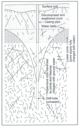
Fig. 8.6. Schematic of a borewell tapping fissured zone in a hard-rock area. (Source: Michael et al., 2008)
Moreover, tubewells are also classified as fully penetrating tubewells or partially penetrating tubewells depending on whether the well screen penetrates the saturated thickness of the aquifer fully or partially. In some special hydrogeologic situations, the drilled hole is terminated at the top of the confined aquifer without penetrating it, and hence no strainer is required; such wells are called cavity wells or non-penetrating wells which are described below. In coastal areas, partially penetrating wells with controlled rate of pumping are used expediently to ‘skim’ the upper layer of fresh water overlying the saline water. Such tubewells are popularly known as skimming wells (Michael et al., 2008; Sarma, 2009).
8.3.3 Cavity Wells
Cavity well is a shallow tubewell drilled in an alluvial formation. If a relatively thin impervious formation consisting of stiff clay, conglomerate or stone is encountered at a shallow depth underlain by an extensive thick sandy confined aquifer, then it is an excellent location for constructing a cavity well. A hole is drilled using the hand boring set, and casing pipe is lowered to rest firmly on the stiff clay layer as shown in Fig. 8.7. Water enters the cavity well through the bottom only and screens are not used in such wells. Thus, the cavity wells do not penetrate the aquifer, and hence they are also known as non-penetrating wells.
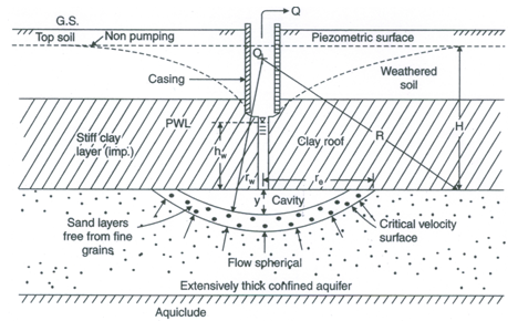
Fig. 8.7. Schematic of a cavity well. (Source: Raghunath, 2007)
A hole of small cross-sectional area is drilled into the sand formation and is developed into a big hollow cavity by pumping at a high rate. In the initial stage of pumping, fine sand comes along with water resulting in the formation of a cavity. During development, the size of the cavity increases till the velocity of groundwater flow at its perimeter becomes small enough to retain the aquifer material in place. With further pumping ultimately equilibrium condition is reached when clean water is discharged. The depth of the cavity at the centre varies from 15 to 30 cm with 6 to 8 m radius of the cavity (Raghunath, 2007).
The flow of water into the cavity is spherical and the yield is low. Cavity wells have usually a shorter lifespan and the failure is caused mainly due to the collapse of the clay roof. Therefore, an essential requirement for a cavity well is that it should have a strong and reliable roof. Since the depth of the cavity well is usually small, deepwell pumps are not necessary. Thus, the capital costs of construction, development and pumpset installation for a cavity well are low, and hence cavity wells are very economical compared to other tubewells.
8.3.4 Filter Points
In deltaic regions, where the aquifer formations mostly consist of coarse sand and gravel, the tubewells are shallow (<15 m deep) and consist of a well screen and a short casing pipe. Such tubewells are called filter points. They are small-diameter (<7.5 cm) tubewells from which water is mostly withdrawn manually (Sarma, 2009).
8.4 Advantages and Disadvantages of Open Wells and Tubewells
The advantages and disadvantages of the open wells and tubewells/borewells are described below (Raghunath, 2007).
8.4.1 Advantages of Open Wells
- Storage capacity of water is available in the well itself.
- They do not require sophisticated equipment and skilled persons for constructions.
- They can be easily operated by installing an ordinary centrifugal pump or by using a manual water-lifting device.
- They can be revitalized by deepening by vertical boring or by blasting at the bottom, or by creating horizontal or inclined bores on the sides of the well to intercept water-bearing formations.
8.4.2 Disadvantages of Open Wells
(1) Large land space is needed for open wells and for the excavated material.
(2) Construction of open wells is slow and laborious.
(3) They are subject to high seasonal fluctuations of water table.
(4) They are very susceptible to drying up in the years of drought or even during the later part of the dry season.
(5) They involve high cost of construction as their depth increases, especially in hard-rock regions.
(6) Deeper aquifers cannot be economically tapped by open wells.
(7) There is an uncertainty of getting good-quality groundwater.
(8) They are vulnerable to contamination unless they are provided with suitable sanitary protection and are sealed from surface water ingress.
8.4.3 Advantages of Tubewells
(1) They do not require much land space and can be constructed even in a limited open area.
(2) They can be constructed quickly due to the use of mechanized equipment.
(3) They can provide sustained supply of water even during drought years. In other words, tubewells provide the only source of water supply during emergencies (i.e., natural and anthropogenic calamities).
(4) They are economical and more reliable, especially when deep and extensive aquifers are encountered.
(5) They can also serve as flowing wells under special hydrogeologic conditions. In this situation, no water-lifting device and energy are required.
(6) They usually provide good-quality groundwater.
(7) They are relatively less vulnerable to contamination.
8.4.4 Disadvantages of Tubewells
(1) They often require costly and sophisticated drilling equipment.
(2) They need skilled personnel and great care for drilling, completion, and maintenance.
(3) Costly pumps are required for lifting groundwater from borewells.
(4) There is a possibility of missing fractures, fissures and joints in hard-rock regions, thereby resulting in many dry borewells.
(5) Rehabilitation of tubewells/borewells is generally very expensive and requires skilled manpower.
(6) Cost of pumping is normally higher than the open wells.
8.5 Selection of Well Site and Type of Well
The following factors should be carefully studied before selecting suitable sites for constructing wells (Raghunath, 2007):
(1) Topography;
(2) Climate;
(3) Vegetation;
(4) Geology;
(5) Porosity, permeability and alteration of rocks;
(6) Joints and faults in rocks;
(7) Folded strata;
(8) Outcrops in the area (if any);
(9) Proximity of surface water bodies (e.g., tanks, rivers, springs, lakes, unlined channels, reservoirs, etc.); and
(10) Depth and yield of the existing tubewells/open wells in the vicinity.
Apart from the above factors, satellite images and hydrogeological maps of the area are very helpful in making a rapid reconnaissance of the area, where a large-scale well construction program is to be implemented. Also, some well-known facts should be kept in mind while selecting well sites. They are: (i) wells located at the lowest level in valleys generally have a greater possibility of yielding large amount of water than the wells located on slopes or ridges; and (ii) the wells located close to rivers/streams, or within the influence of other surface water bodies like lakes, ponds/tanks and reservoirs will have better yields and will ensure reliable water supply.
Once the preliminary assessment of well sites has been made, and there is no constraint of money and time, geophysical methods of groundwater exploration are also employed, of which electrical resistivity method has been found to be quite helpful in the selection of well sites. In addition, subsurface exploration can be done by test drilling and logging techniques can be used to explore various rock formations at different depths and their water-bearing properties. However, the use of subsurface exploration techniques is essential and economically justified for large water supply projects only.
After determining the purpose and the quantity of water required, the type of well suitable for the purpose can be selected. Besides these two major factors, the following information is also helpful in identifying a suitable type of well: (i) availability of land space, (ii) stratigraphy and hydrogeologic characteristics of the subsurface formations; (iii) seasonal fluctuation of groundwater levels; (iv) cost of well construction and that of water-lifting devices; and (v) the economics of groundwater pumping, which can be ignored if there is no other reliable source of potable water in an area.
As to the quality of groundwater, the groundwater present in igneous rocks is generally acidic in nature and low in mineral contents. The groundwater is hard and brackish in basalts and shales as well as in the alluvium of deltaic areas close to the sea. However, groundwater of good-quality is generally expected from river alluviums and sandstones.
References
Michael, A.M., Khepar, S.D. and Sondhi, S.K. (2008). Water Well and Pump Engineering. Second Edition, Tata McGraw Hill Education Pvt. Ltd., New Delhi.
Raghunath, H.M. (2007). Ground Water. New Age International (P) Limited, New Delhi.
Sarma, P.B.S. (2009). Groundwater Development and Management. Allied Publishers Pvt. Ltd., New Delhi.
Todd, D.K. (1980). Groundwater Hydrology. John Wiley & Sons, New York.
Suggested Readings
Michael, A.M., Khepar, S.D. and Sondhi, S.K. (2008). Water Well and Pump Engineering. Second Edition, Tata McGraw Hill Education Pvt. Ltd., New Delhi.
Sarma, P.B.S. (2009). Groundwater Development and Management. Allied Publishers Pvt. Ltd., New Delhi.
Raghunath, H.M. (2007). Ground Water. Third Edition, New Age International Publishers, New Delhi.
Todd, D.K. (1980). Groundwater Hydrology. John Wiley & Sons, New York.
Last modified: Friday, 7 February 2014, 11:51 AM