Site pages
Current course
Participants
General
Module 1. Introduction to Theory of Machine
Module 2. Planar Mechanism
Module 3. Velocity and Acceleration Analysis
Topic 4
Topic 5
Topic 6
Topic 7
Topic 8
Topic 9
Topic 10
Lesson 6.
6.1 SLIDER CRANK MECHANISM ANALYSIS BY RELATIVE VELOCITY METHOD
Angular velocity of link OA is given ω and velocity of point A can be given by, Va = ω×OA = VAO in the clockwise direction about O. Va is perpendicular to OA. So we know the direction and magnitude of Va. The velocity of slider B is along OB. The configuration and velocity diagram for this problem is given below.
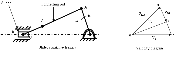
Fig. 3.5
Step 1. Take any point o and draw vector oa such that oa= ω × OA=VAO, perpendicular to OA in some suitable scale as shown in the velocity diagram.
Step 2. The velocity of point B with respect to A (VBA) is perpendicular to AB. From a draw a vector ab perpendicular to the line AB.
Step 3. The velocity of slider B is along the line of stroke OB, from o draw a line parallel to OB which will intersect vector ab at b. The vector ob represent the velocity of slider B (VB).
The velocity of any point C on the connecting rod can be determined by the help of relation:
\[\frac{{{\mathbf{ac}}}}{{{\mathbf{ab}}}} = \frac{{{\text{AC}}}}{{{\text{AB}}}}{\text{ or }}{\mathbf{ac}} = {\mathbf{ab}} \times \frac{{{\text{AC}}}}{{{\text{AB}}}}\]
The point c can be located on the velocity diagram. Join o with c. vector oc represents the absolute velocity of point C with respect to O.
Example 3.1 In the mechanism as shown below, the crank O2A rotates at 600 r.p.m. in the anticlockwise direction. The length of link O2A= 12 cm and of link O1B= 60 cm. Find
a. Angular velocity of link O1A.
b. Velocity of slider at B.
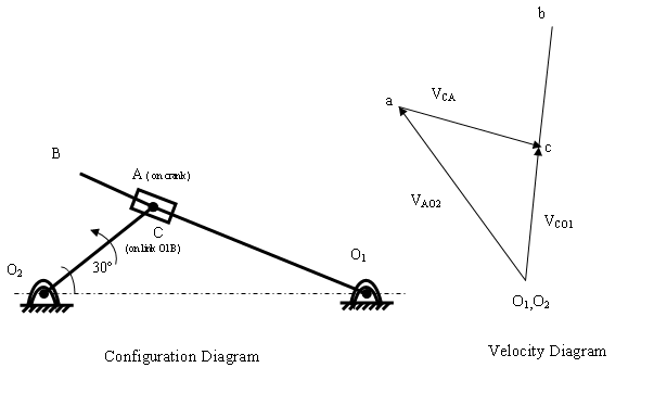
Fig. 3.6
Solution:
Given: N=600 r.p.m
\[\omega={\text{ }}\frac{{{\text{2}}\pi{\text{N}}}}{{{\text{6}}0}} = \frac{{{\text{2}}\pi\times {\text{6}}00}}{{{\text{6}}0}} = {\text{2}}0{\text{ }}\pi {\text{ rad}}/{\text{sec}}\]
The velocity of A with respect to O2
\[{{\text{V}}_{{\text{AO2}}}}= \omega\times{{\text{O}}_{\text{2}}}{\text{A}}={\text{2}}0\pi\times \frac{{{\text{12}}}}{{{\text{1}}00}} = {\text{7}}.{\text{53 m}}/{\text{s}}\]
In the configuration diagram let us take a point C on the link O1B. The velocity diagram can be drawn as explain below.
Step 1. O1 and O2 are fixed points on the configuration diagram so they are taken as single point (o1,o2) on the velocity diagram. The velocity of point A with respect to O2, VAO2 = 7.53 m/s is drawn as vector o2a in some suitable scale perpendicular to O2A.
Step 2. The velocity of point C with respect to A, VCA along the path of slider, O1B. From a draw a vector ac representing VCA along O1A. This will contain point c.
Step 3. The velocity of point C with respect to O1 is VCO1 and it will be perpendicular to O1A.Then from o1 draw a vector o1c representing VCO1 this will intersect ac at point c.
Step 4. Locate the point b corresponding to point B such that
\[\frac{{{{\mathbf{o}}_{\mathbf{1}}}{\mathbf{b}}}}{{{{\mathbf{o}}_{\mathbf{1}}}{\mathbf{c}}}} =\frac{{{{\text{O}}_{\text{1}}}{\text{B}}}}{{{{\text{O}}_{\text{1}}}{\text{C}}}}\]
o1b= 5.55 m/s by measurement
o1b=VBO1
Angular velocity of link O1A
\[{\omega_{{\text{O1A}}}}={\omega _{{\text{O1B}}}}=\frac{{{{\text{V}}_{{\text{BO1}}}}}}{{{{\text{O}}_{\text{1}}}{\text{B}}}}= \frac{{{\text{5}}.{\text{55}}}}{{0.{\text{6}}0}}\]
= 9.25 rad/sec
(anticlockwise direction)
6.2 INSTANTANEOUS CENTRE OF ROTATION
A rigid body undergoing in plane motion, there always exist a point in the plane of motion at which the velocity is zero at that particular instant. This point is called instantaneous centre of rotation or I-centre. It may or may not lie on the body. If the location of this point is determined then we can simplify the velocity analysis. To locate the I-centre, we use the fact that the velocity of a point on a body is always perpendicular to the position vector from I-centre to that point. If the velocity at two points A and B are known, I-centre will lie at the intersection of the perpendiculars to the velocity vectors through A and B.
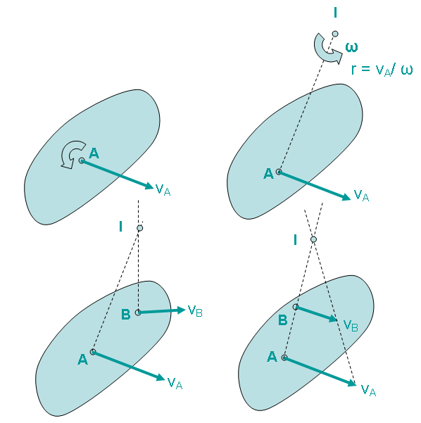
Fig. 3.7 I-centre of a body
If the velocity vectors at A and B are perpendicular to the line AB, I-centre will lie at the intersection of the line AB with the line joining the extremities of the velocity vectors at A and B.If the velocity vectors are equal & parallel, I-centre will lie at infinity and the angular velocity is zero (pure translation).
6.3 NUMBER OF I-CENTRE
The number of I-centre ‘N’ in a mechanism is given by
\[{\text{N}} = \frac{{n{\text{ }}(n - 1)}}{{\text{2}}}\]
Where n = No. of links
The number of I-centre in a four bar mechanism will be \[\frac{{{\text{4}} \times \left( {{\text{4}} - {\text{1}}} \right)}}{{\text{2}}} = {\text{6}}\] .
6.4 HOW TO LOCATE I-CENTRE
There are two methods to locate the I-centre
1. by using rules to locate I-centre by inspection
2. by applying Aronhold-Kennedy Theorem
Rules to locate I-centre
- The centre of the pivot is the I-centre for two links in the pivoted joint.
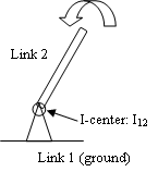
Fig. 3.8
- The I-centre lies at infinity perpendicular to the path of motion of the slider.
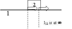
Fig. 3.9
- In pure rolling or in case of no slip between the two links. The I-centre will lie at the point contact between the two links.
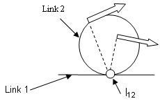
Fig. 3.10
Last modified: Tuesday, 25 March 2014, 9:27 AM