Site pages
Current course
Participants
General
Module 1. Introduction to Theory of Machine
Module 2. Planar Mechanism
Module 3. Velocity and Acceleration Analysis
Topic 4
Topic 5
Topic 6
Topic 7
Topic 8
Topic 9
Topic 10
Lesson 8.
8.1 ACCELERATION ANALYSIS
The rate of change of velocity with respect to time is known as acceleration. It has magnitude as well as direction. So, it is a vector quantity. Consider two points A and B on a rigid link. Point B moves relative with respect to A with an angular velocity of ω rad/s and angular acceleration of α rad/s2.VBA is the velocity of point B relative to A is perpendicular to the line joining A and B (as shown in figure 3.16a).VBA is equal to ω × AB. Acceleration has two components radial or centripetal and tangential.
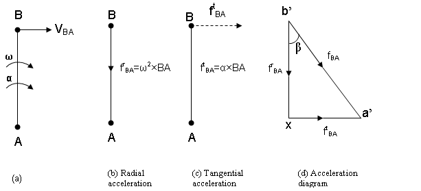
Fig. 3.16 acceleration components
8.1.1 RADIAL OR CENTRIPETAL COMPONENT OF ACCELERATION
The magnitude of radial component is given by frBA= ω2×BA where frBA= Radial component of acceleration of point B respect to point A (as given in fig: 3.16b). Its direction is given from B to A. When the angular velocity of a rotating link or a particle moving in a circular path is not constant, but is subjected to an angular acceleration (with consequent peripheral or linear acceleration), the resultant acceleration may be found by adding the vectors representing the centripetal and peripheral (or tangential) accelerations. Since the centripetal acceleration is always radial and perpendicular to the instantaneous direction of the motion and the peripheral acceleration is perpendicular to the radius, these two accelerations are always mutually perpendicular and the resultant acceleration is easily found by applying the wall known relationship which exist between the sides of a right angled triangle, that is by extracting the square root of the sum of the squares of the respective accelerations.
8.1.2 TANGENTIAL COMPONENT OF ACCELERATION
It can be defined as the rate of change velocity VBA in the tangential direction. Its magnitude will be equal to α×BA. It is represented by ftBA; the tangential component of acceleration of B with respect to A. ftBA is perpendicular to BA and parallel to VBA.
The total acceleration of point B with respect to A is the vector sum of their components of radial and tangential acceleration. This can be written as
\[{{\text{f}}_{{\text{BA}}}}={\text{}}{{\text{f}}^{\text{r}}}_{{\text{BA}}}+{\text{}}{{\text{f}}^{\text{t}}}_{{\text{BA}}}={\text{}}{\omega ^{\text{2}}} \times {\text{BA}} + {\text{ }}\alpha\times {\text{BA}} = {\text{ }}\left( {{\omega ^{\text{2}}} + {\text{ }}\alpha } \right){\text{}} \times {\text{ BA}}\]
Here fBA is the total acceleration of B with respect to A
8.1.3 How to draw acceleration diagram
Step 1. Draw b’x = frBA in some suitable scale parallel to AB and its direction will be from B to A.
Step 2. From point x draw xa’ = ftBA = α×BA which is perpendicular to AB. α is known in this case.
Step 3. Join a’ with b’ which shows fBA, which represents the total acceleration of B with respect to A. The acceleration of B relative to A is inclined at an angle of β with AB.
\[{\text{Tan }}\beta= \frac{\alpha }{{{\omega ^{\text{2}}}}}\]
When α = 0, AB rotates at the uniform angular velocity, ftBA = 0 and thus frBA represents the total acceleration.
When ω = 0, A has a linear motion, frBA = 0 and thus the tangential acceleration is the total acceleration.
Example: 3.3 A motor-car passes round a curve of 30.5 m radius and at a given instant has a speed of 82 km/h (or 8.89 m/s). The car is accelerating at the rate of 16 km/h in 3 sec. find the resultant acceleration.
Sol:
Centripetal acceleration, ƒr = rω2 = v2/r
ƒr = (32000/3600)2 / 30.5 = 2.59 m/s2
Tangential acceleration, ƒt = (16000/3600)/3 = 1.48 m/s2
Resultant acceleration, ƒ = √(2.592 + 1.482) = √8.8985 = 2.983 m/s2
Example 3.4 The crank of a slider crank mechanism rotates a constant speed of 300 r.p.m. The crank is 150 mm and the connecting rod is 600 mm long. Determine: the angular velocity and angular acceleration of the connecting rod when the crank makes the angle of 450 with form the inner dead centre.
Solution.
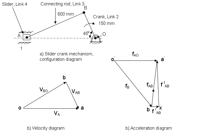
Fig. 3.17
The crank OB = 150 mm = 0.15 m
NBO=300 r.p.m.
\[{\omega _{{\text{OB}}}} = \frac{{{\text{2}}\pi\times {\text{3}}00}}{{{\text{6}}0}} = {\text{ 31}}.{\text{4 rad}}/{\text{s}}\]
VBO= ω OB × OB= 31.4 × 0.15= 4.71 m/s
Velocity diagram is drawn by following these steps
Step 1. VBO, the velocity of point B with respect to O is known and it is perpendicular to OB. Take any point o and draw vector ob which will represent VBO.
Step 2. VAB is perpendicular to AB, from b draw a vector ba perpendicular to AB representing VAB.
Step 3. VA ,the velocity of slider is along path OA. From o draw vector oa which will intersect vector ba at point a.
By measurement oa=VA=4 m/s
ba=VAB=3.34 m/s
The radial acceleration of B with respect to O,frBO is given as
\[{{\text{f}}^{\text{r}}}_{{\text{BO}}}={{\text{f}}^{\text{r}}}_{\text{B}}=\frac{{{{\text{V}}^{\text{2}}}_{{\text{BO}}}}}{{{\text{OB}}}}= \frac{{{{\left( {{\text{4}}.{\text{71}}} \right)}^{\text{2}}}}}{{0.{\text{15}}}} = {\text{147}}.{\text{8 m}}/{{\text{s}}^{\text{2}}}\]
ftBO=0 as crank rotates with the constant speed
Radial acceleration of A with respect to B is given as
\[{{\text{f}}^{\text{r}}}_{{\text{AB}}}=\frac{{{{\text{V}}^{\text{2}}}_{{\text{AB}}}}}{{{\text{AB}}}}=\frac{{{{\left({{\text{3}}.{\text{34}}} \right)}^{\text{2}}}}}{{0.{\text{6}}0}} = {\text{18}}.{\text{5m}}/{{\text{s}}^{\text{2}}}\]
The acceleration diagram is drawn by following these steps
Step 1. Draw vector o’b’ = frBO parallel to BO and 147.8 m/s2 in magnitude.
Step 2. The radial acceleration of A with respect to B, frAB is known in magnitude i.e. 18.5 m/s2 and parallel to AB. from b’ draw vector b’x=frAB. from x draw xa’ perpendicular to b’x representing tangential component of acceleration of A with respect to B.
Step 3. The acceleration of slider A with respect to O, fAO is along the line of stroke of OA. From o’ draw vector o’a’ representing fAO. o’a’ intersects xa’ at point a’. Now join o’ to a’. Thus o’a’ is fAO=fA
By measurement fA=o’a’= 109 m/s2
Angular velocity of the connecting rod is given by
\[{\omega _{{\text{AB}}}}=\frac{{{{\text{V}}_{{\text{AB}}}}}}{{{\text{AB}}}}= \frac{{{\text{3}}.{\text{34}}}}{{0.{\text{6}}0}} = {\text{5}}.{\text{56 rad}}/{\text{s}}\]
Angular acceleration of the connecting rod AB, αAB is given by
\[{\alpha_{{\text{AB}}}}=\frac{{{{\text{f}}^{\text{t}}}_{{\text{AB}}}}}{{{\text{AB}}}}={\text{ }}\frac{{{\text{1}}0{\text{7}}.{\text{5}}}}{{0.{\text{6}}0}} = {\text{179}}.{\text{1 rad}}/{{\text{s}}^{\text{2}}}\]
(ftAB=xa’=107.5 by measurement)
Last modified: Tuesday, 25 March 2014, 10:54 AM