Site pages
Current course
Participants
General
Module 1. Introduction to Theory of Machine
Module 2. Planar Mechanism
Module 3. Velocity and Acceleration Analysis
Topic 4
Topic 5
Topic 6
Topic 7
Topic 8
Topic 9
Topic 10
Lesson 24.
24.1 Consider a pulley 1 driving the pulley 2. The pulley 1 is called driver and pulley 2 is called driven. So velocity ratio may be defined as the ratio of speed of driven to that of driver or ratio of diameter of driver to that of driven.
Mathematically the equation is:
\[\frac{{{{\text{N}}_{\text{2}}}{\text{ }}}}{{{{\text{N}}_{\text{1}}}}} = \frac{{{{\text{D}}_{\text{1}}}}}{{{\text{ }}{{\text{D}}_{\text{2}}}}}\]
N1 = Speed of driver pulley in rpm
N2 = Speed of driven pulley in rpm
D1 = Diameter of driver pulley in mm
D2 = Diameter of driven pulley in mm
When the thickness of the belt (t) is considered, then velocity ratio is given by
\[\frac{{{{\text{N}}_{\text{2}}}}}{{{{\text{N}}_{\text{1}}}}} = {\text{ }}\frac{{\left( {{{\text{D}}_{\text{1}}} + {\text{ t}}} \right){\text{ }}}}{{\left( {{{\text{D}}_{\text{2}}} + {\text{t}}} \right)}}\]
24.2 SLIP OF BELT DRIVES
The forward motion of the driver without carrying the belt with it is called slip of the belt and is generally expressed in percentage. For slippage velocity ratio is given by
\[\frac{{{{\text{N}}_{\text{2}}}}}{{{{\text{N}}_{\text{1}}}}}={\text{}}\frac{{\left({{{\text{D}}_{\text{1}}}+{\text{t}}}\right){\text{}}}}{{\left({{{\text{D}}_{\text{2}}} + {\text{t}}} \right)}}\times {\text{ }}\left( {{\text{1}} - \frac{{\text{S}}}{{100}}} \right)\]
Where S= S1+S2 (total percentage of slip)
S1 = Percentage slip between driver and the belt and
S2= Percentage slip between belt and the follower
24.3 Length of open belt drive
Consider an open belt drive; both the pulleys rotate in the same direction as shown in the figure 5.7
Let r1 and r2 be radii of larger and smaller pulley
X= distance between the centres of two pulleys i.e. (C1, C2)
L= Total length of the belt
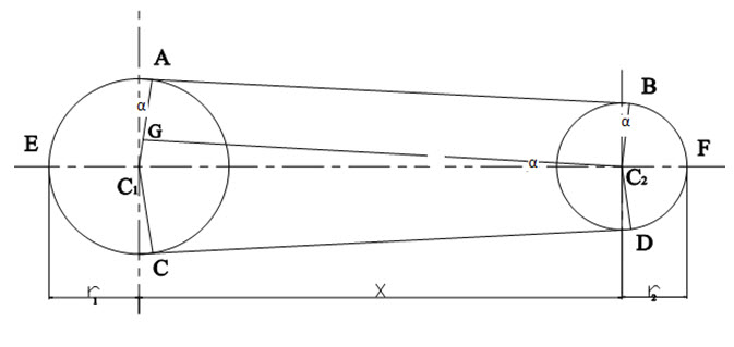
Fig. 5.7 Length of open belt drive
Let the belt leaves the larger pulley at A and C and smaller pulley at B and D. Through C2 draw C2G parallel to AB.
From the figure, C2G will be perpendicular to C1A.
Let the angle GC2C1=α radians
We know that length of belt is given by
L= Arc CEA+AB+Arc BFD+DC
=2(Arc AE+AB+Arc BF)
From the figure,
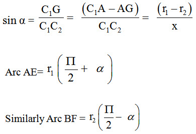
AB= GC2= [(C1C2)2 – (C1G) 2]1/2= [x2-(r1-r2)2]1/2
Expanding by binomial theorem
Substituting the values of arc AE from equation, arc BF and AB from equations we get

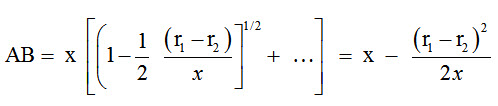
24.4 Ratio between belt tensions
A driven pulley rotating in clockwise direction is shown in figure 5.8
Let T1 = Tension on tight side of the belt
T2 = Tension on slack side of the belt
θ = Angle of contact of belt with pulley in radians
µ = Coefficient of friction between the belt and pulley.
Considering a small portion of belt XY in contact with the pulley. X makes angle δθ at the centre of the pulley. Let T be the tension in the belt at X and (T + δT) be the tensions in the belt at Y.
Fig 5.8 Ratio of driving tensions
The belt portion XY is in equilibrium under the action of following forces:
1. Tension T in belt at X.
2. Tension T + δT in belt at Y.
3. Frictional reaction R at U.
4. Frictional force µR between belt and pulley.
Now again solving the forces expression in horizontal direction
µR = (T + δT) cos (δθ / 2) - T cos (δθ / 2)
Since δθ is very small
cos (δθ / 2) = 1
µR + T = (T + δT)
µR = δT …(1)
and resolving the force is vertical reaction.
R = T sin (δθ / 2) + (T + δT) sin (δθ/2)
Since, δθ is very small, so
R = T δθ/2 + (T + δT) δθ/2 = T δθ …(2)
From equations (1) and (2)
µ(T δθ) = δT (neglecting δT. δθ / 2 )
δT / T = µ δθ
On integration, we get
T2∫T1 δT/T = ∫oθ µdθ
loge T1 / T2 = µθ
T1 / T2 = (e)µθ
24.5 Power transmitted by belt drive
Power transmitted, P = (T1 - T2) V (Watt)
V is the velocity of the belt = \[ = \frac{{{\text{ }}{{\text{D}}_{\text{1}}}{{\text{N}}_{\text{1}}}}}{{60}}\] (m/sec)
24.6 Tension in the belts
The initial tension (T0) ensures that the belt would not slip under designed load. Belts are mounted on the pulleys with a certain amount of tension T0. At rest, the forces acting on the two sides of belts are equal. As the power is transmitted, the tension on the tight side increases and tension on the slack side decreases.
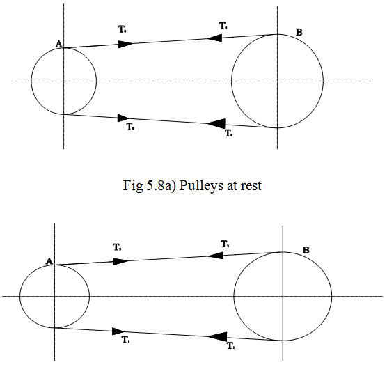 Fig 5.8 (b) Pulleys Working
Mathematically Initial tension is given by
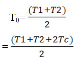
Where T1 and T2 are tensions on tight side and slack side and Tc is the centrifugal tension given by
Tc=mv2
Where m= mass of belt per unit length and V=Velocity of belt in m/s
24.7 Condition for the transmission of Maximum power
Power transmitted by belt drive is given by
P= (T1-T2) V…………………………….(1)
Where T1= Tension in the belt on tight side
T2= tension in the belt on slack side
V= velocity of belts
Also \[\frac{{{{\text{T}}_{\text{1}}}}}{{{{\text{T}}_{\text{2}}}}} = {{\text{e}}^\mu }^\theta \]
Substituting the value of T2, we get
\[= ({{\text{T}}_{\text{1}}}--{\text{ }}\frac{{{{\text{T}}_{\text{1}}}{\text{ }}}}{{{{\text{e}}^{\mu \theta }}}}){\text{V}} = {\text{ }}{{\text{T}}_{\text{1}}}({\text{1}} - \frac{{\text{1}}}{{{{\text{e}}^{\mu \theta }}}}){\text{V}} = {{\text{T}}_{\text{1}}}.{\text{V}}.{\text{Z}}\] ……………… (2)
Where
\[{\text{Z}} = {\text{1}} - \frac{{{\text{1 }}}}{{{{\text{e}}^{\mu \theta }}}}\]
Also maximum tension (T) in the belt considering centrifugal tension (Tc) is given by
T=T1+Tc
Substituting the value T1 in equation (2)
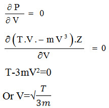
P= (T-Tc) V.Z= (T.V-mV3) Z
Differentiating with respect to V for maximum power and equate to zero
Last modified: Wednesday, 26 March 2014, 11:22 AM