Site pages
Current course
Participants
General
Module 1:Water Resources Utilization& Irrigati...
Module 2:Measurement of Irrigation Water
Module 3: Irrigation Water Conveyance Systems
Module 4: Land Grading Survey and Design
Module 5: Soil –Water – Atmosphere Plants Intera...
Module 6: Surface Irrigation Methods
Module 7: Pressurized Irrigation
Module 8: Economic Evaluation of Irrigation Projec...
Topic 9
LESSON 37 Design of Sprinkler Irrigation System-I
37.1 General Considerations
A sprinkler irrigation system needs to be laid and designed properly to suit the conditions of a particular site to achieve high efficiencies. The choice of sprinkler system depends on i) land topography that cannot be properly leveled owing to the subsoil being exposed and cost involved in land leveling ii) soil texture, particularly infiltration rate of the soil so that the application or precipitation rate of the system is less than the infiltration rate of the soil iii) available water resources and eventually matching the capacity of sprinkler system with the water requirement of the crops and, the system with high water application efficiency, and iv) cost effective from the point of crop production economics. This lesson deals with various aspects required for the design of sprinkler irrigation system.
37.2 Inventory of the Land and Water Resources
The inventory of resources includes following:
i) Topographical map of the Area: The topographical map of the field needs to be prepared. The map should include the field boundaries and the locations of the bunds, farm roads building and location of water resources. The map may also include possibly the areas selected for cultivation of different crops in the field. This is required for knowing the total area to be irrigated for different crops and then estimating the quantity of water required for each irrigation. The map should also include the contour map of the area. The contour map enables to determine the slope of the field, if any, in both the direction. The slope is required to decide the layout and placement of the pipe network (main, sub main and laterals) and computation of the elevation difference which is required for the design of pipes in terms of its diameter and length.
ii) Water Resources: The information on quantity and quality of available water resources is required for design of sprinkler system. The quantity of the water resources in terms of the seasonal availability of the water; and discharge available for irrigating the field and duration for which it is available per day are required to match with the crop water requirement. This information is particularly required for deciding whether the entire area of the proposed field or the portion of the area of the field can be irrigated. The location of the source of water in the field is desired to estimate the length and diameter of the main, sub main and lateral pipes. The water quality parameters include EC, pH and SAR. Some crops may have detrimental or scorching effect on leaves, if water having high soluble salts used for sprinkling water. The quality of water is thus important to decide its suitability for crops for sprinkler irrigation. This information is also required for deciding the irrigation frequency. The water with high soluble salt contents may be required to be applied more frequently compared to good quality water.
iii) Crops to be Irrigated: The information on crops, its root zone depth, crop coefficient, and allowable depletion level is required for computing the water requirement of the crops and irrigation frequency. The climatic and soil parameters are required to determine crop water requirement.
iv) Soils: The soil parameters such as field capacity, wilting point, bulk density and infiltration rate are used for irrigation system design. Field capacity, wilting point, bulk density are required for estimating the available soil water in the root zone. Allowable soil water depletion for a specified crop and climate data are required for computing the depth of irrigation and frequency of irrigation. The information on infiltration rate is used in selecting the nozzle size, type of nozzle and lateral spacing.
v) Climate: The weather parameters such as pan evaporation, rainfall, temperature, relative humidity, wind speed and sunshine hours are required to compute the water requirement of the crops. The peak water requirement estimation requires peak summer weather parameters such as solar radiation, temperature, humidity etc.
vi) Availability of Power Source: The type of source of power can be electricity or diesel or both. Irrigation system can be planned and designed based on the assured timings of availability of power supply.
37.3 Types of Sprinkler Systems Layout
The layout of sprinkler system is made based on water source and location of water supply. The source of water supply for sprinkler irrigation can be surface water (river, canal, pond etc.) or ground water (a tube well or open well). When deciding the location of well, it can be located at a corner or, at the center of the farm to minimize the length of main pipe. The source at higher elevation is desirable. The layout of the mains depends on the location of the well. Fig. 37.1 shows the layout of stationary water source and pump at center of field and laterals are moved to successive position up one side of the main and then down on the other. Fig. 37.2. shows fully portable pumping set unit. In a Portable sprinkler system field channel runs along one edge of the farm. In this system a portable pumping set and sprinkler unit with the lateral extending to the field are used to draw water directly from the channel and distribute it through the sprinklers. Another alternative is to have a permanent pumping plant at the source and distribute water in buried pressurized pipelines. These pipelines will usually run down the center of the field so that the outlets offer little hindrance to tillage and other farm operations.
To obtain a reasonable degree of uniformity in the discharge of each sprinkler, the mains should run in the direction of the steepest slope, with the laterals at right angles and as close as on contours. Generally design is made considering running on level land. If the lateral slopes upgrade appreciably, it is difficult to design for a very long pipe length. If it slopes downgrade, the length can be longer than usual, but rarely does the slope remains uniform for each setting.
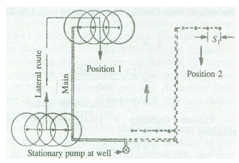
Fig. 37.1. Layout plan for sprinkler irrigation system for stationary water Source of well and pump. (Source: Michael, 2010)
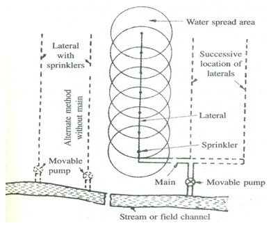
Fig. 37.2. Typical field layouts for fully portable sprinkler units drawing water from streams or field channels. (Source: Michael, 2010)
37.3.1 Layout for Set-Move Sprinkler System
Different layouts for set-move sprinkle systems are shown through Figs. 37.3 (a), (b), (c), (d), (e), & (f). The guide lines for set-move sprinkler system are stated below:
i) Mains should be laid up and downhill.
ii) Laterals should be laid across slope or nearly on the contour as for as possible.
iii) For multiple lateral option, lateral pipe sizes should be limited to not more than two diameters.
iv) If possible, water supply nearest to the center of area should be chosen.
v) Layouts should facilitate minimal lateral movement during a crop season.
vi) Differences in number of sprinklers operating for various setups should be minimum.
vii) Booster pumps should be considered where small portions of field would require high pressure at the pump.
viii) Layout should be modified to apply different rates and amounts of water where soils are greatly different in the design area.
ix) Mainline and sub main layout is keyed to lateral layout.
x) When laterals run across prominent slopes, mainlines or sub mains will normally run up and down the slopes Fig 37.3(a) and (b).
xi) When it is necessary to run laterals up and down hill, the mainlines or sub mains should be located on ridges Fig 37.3(c), (d), (e) & (f) to avoid laterals to run uphill.
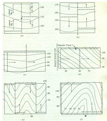
Fig. 37.3. Layouts for set-move sprinkle systems. (Source: James Larry, 1988)
(a) Layout on moderate, uniform slopes with water supply at center (b) Layout illustrating use of odd number of laterals to provide required number of operating sprinklers. (c) Layout with gravity pressure where pressure gain approximates friction loss and allows running laterals downhill. (d) Layout illustrating area where laterals have to be laid downslope to avoid wide pressure variation caused by running laterals upslope. (e) Layout with two main lines on ridges to avoid running laterals uphill. (f) Layout with two main lines on the sides of the area to avoid running the laterals uphill.
37.3.2 Split Lateral Layouts
i) In this layout mainlines and sub mains are located such that set move laterals may operate on either side of them (Fig. 37.3 (a), (b) and (e)).
ii) They minimize friction loss because of shorter laterals.
iii) Split layouts also allow set-move laterals to be rotated around mainlines (Fig.37.3 (a), (b)).
iv) Labor requirement is reduced by eliminating the need to move lateral pipes back to starting point (Fig 37.3(c) and 37.3(d)).
37.4 Sprinkler System Design Parameters
37.4.1 Sprinkler Discharge Considering Area of Coverage: The actual selection of different components of the sprinkler system is based on specifications furnished by the manufacturers of the equipment. The selection depends on wetting diameter of nozzle, at a given operating pressure at nozzle, sprinkler discharge, combination of sprinkler spacing and lateral moves, application rate suiting to soil and wind conditions. The required discharge of an individual sprinkler is a function of the water application rate and the two-way spacing of the sprinklers. It may be determined by the following equation:
![]() (37.1)
(37.1)
in which,
q = required discharge of individual sprinkler,
S1 = spacing of sprinklers along the laterals, m
Sm= spacing of laterals along the main, m
I = optimum application rate, mm
The values of maximum rate of application for various soil types and slopes are presented in Table 37.1.
Table: 37.1 Maximum application rates for different types of soils
|
Soil texture and profile |
0 to 5% slope |
5 to 8 % slope |
8 to 12 % slope |
|
Coarse sandy soils to 2 m |
5.10 |
3.75 |
2.54 |
|
Coarse sandy soils over more compact soils |
3.75 |
2.54 |
1.9 |
|
Light sandy loams to 2 m |
2.54 |
2.03 |
1.5 |
|
Light sandy loams over more compact soil |
1.9 |
1.27 |
1.02 |
|
Silt loam to 2 m |
1.27 |
1.02 |
0.76 |
|
Silt loams over more compact soils |
0.76 |
0.63 |
0.38 |
|
Heavy textured clays or clay loams |
0.38 |
0.25 |
0.20 |
Source: Adapted from SCS (1993).
37.4.2 Height of Sprinkler Riser Pipes: Sprinklers are located just above the crops to be irrigated and, therefore, the height of the risers depend upon the maximum height of the crop. To avoid excessive turbulence in the riser pipes the minimum height of riser is 300 mm for 25 mm diameter and 150 mm for 15 mm to 20 mm diameter.
37.4.3 Sprinkler Spacing: The uniformity of water distribution from sprinklers depends on the operating pressure, wind velocity, rotation of sprinklers, spacing between sprinklers and laterals. The spacing of sprinklers on laterals and the laterals spacing are adjusted for obtaining maximum uniformity for given condition. Greater depth of water accumulate near sprinkler head and depth decreases gradually with distance from the sprinklers. Therefore there is a necessity of overlapping of the spray pattern of the individual sprinkler, to obtain uniform depth of water application. Sprinklers are arranged along a lateral such that the diameter of the water spread area of sprinkler is overlapped. If there is a wind of considerable speed, the spacing between sprinklers is further reduced as given in Table 37.2.
Table. 37.2. Overlapping of sprinkler spacing for different wind speeds.
|
Sl.No. |
Average wind speed |
Spacing |
|
1 |
No wind |
65% of the water spread area of a sprinkler |
|
2 |
0-6 km/h |
60% of the water spread area of a sprinkler |
|
3 |
6.5 to 13 km/h |
50% of the water spread area of a sprinkler |
|
4 |
Above 13 km/h |
30% of the water spread area of a sprinkler |
Source: Adapted from SCS (1993)
37.4.4 Capacity of sprinkler system: The capacity of a sprinkler system is a important design parameter. This is estimated after knowing the total area to be irrigated by a sprinkler irrigation system. The formula to compute system capacity is given by
Q = 2780 ![]() (37.2)
(37.2)
in which,
Q = discharge capacity of the pump,
A = area to be irrigated, ha
d = net depth of water application, cm
F = number of days allowed for the completion of one irrigation
H = number of actual operating hours day-1
E = water application efficiency, per cent
37.4.5 Sprinkler Discharge: The discharge of a sprinkler is estimated by knowing the diameter of nozzle and operating pressure available at the nozzle by following formula.
Q = C A ![]() (37.3)
(37.3)
where,
Q = discharge, cm3 s-1
C = sprinkler discharge coefficient which vary from 0.80 to 0.95
A = cross – sectional area of nozzle or orifice, cm2
g = acceleration due to gravity, cm/s2, and
h = pressure head, cm
37.4.6 Spread of Sprinkler: The area covered by a rotating head sprinkler can be estimated from the formula stated in equation 37.4.
![]() (37.4)
(37.4)
where,
R = radius of the wetted area covered by sprinkler, m
d = diameter of nozzle, m
h = pressure head at nozzle, m
The maximum coverage is attained when the jet emerges from the sprinkler nozzle at angle between 300 and 320.
37.4.7 Rate of Water Application or Precipitation Intensity: The rate of water application by an individual nozzle is estimated by the formula as stated below.
![]() (37.5)
(37.5)
where,
Ra = rate of water application, cm
Q = rate of discharge of sprinkler,
A = wetted area of sprinkler, m2
References
Michael, A. M. (2010). Irrigation Theory and Practice, Vikas Publishing House Pvt. Ltd, Noida, India: 591-592.
James, Larry G. (1988). Principles of Farm Irrigation System Design, John Wiley and Sons, Inc., New York: 235.
U.S. Department of Agriculture, Natural Resources Conservation Service. (1993). Soil Survey Manual. Agricultural Handbook No. 18, chapter 3. U.S. Government Printing Office, Washington, DC.
Suggested Readings
Heermann, D.F. and Kohl, R.A. (1980). Fluid Dynamics of Sprinkler systems. (Chapter 14 in Design and Operation of Farm Irrigation systems edited by Jensen, M.E.) ASAE Monograph 3. St. Joseph, MI.
Last modified: Saturday, 15 March 2014, 11:02 AM