Site pages
Current course
Participants
General
Module 1:Water Resources Utilization& Irrigati...
Module 2:Measurement of Irrigation Water
Module 3: Irrigation Water Conveyance Systems
Module 4: Land Grading Survey and Design
Module 5: Soil –Water – Atmosphere Plants Intera...
Module 6: Surface Irrigation Methods
Module 7: Pressurized Irrigation
Module 8: Economic Evaluation of Irrigation Projec...
Topic 9
LESSON 40 Evaluation of Rotating Head Sprinklers and Operation of Sprinkler System
40.1 Evaluation of a Sprinkler Head
The sprinkler head is evaluated based on the water distribution pattern from the sprinkler nozzle, discharge of sprinkler nozzle, radius of throw, sprinkler rotation and precipitation or water application depth collected in a standard catch can under set of condition specified in the BIS (IS: 10802-1984).
40.1.1 Site Conditions and Test Equipment
i) Sprinkler site: The sprinkler should be located in an area where the surface is smooth or where vegetative growth is less than 150 mm in height. The surface grade should not exceed 2 percent within the wetted area of sprinkler under test.
ii) Collector Description and Location: The collectors or catch cans used for any one test should be such that the water does not splash in or out. The type of collector should be identified and recorded on the data sheet. If an evaporation suppressant is used its type and method of application should be identified and recorded on the data sheet. The spacing of the collectors depends on the radious of throw of the sprinklers and given in Table 40.1.
Table 40.1. Spacing of collectors
|
Sprinkler radius of throw, m |
Maximum collector spacing center to center, m |
|
0.3-3 |
0.30 |
|
3-6 |
0.60 |
|
6-12 |
0.75 |
|
>12 |
1.50 |
iii) Sprinkler mounting: The sprinkler nozzle height above the nearest collector(s) for test purposes is given in Table: 40.2.
Table 40.2. Nozzle heights
|
SL. No. |
Sprinkler type |
Maximum nozzle height above collector (mm) |
|
1 |
Riser mounted, rotating sprinkler of not more than 30 mm nominal inlet size |
915 |
|
2 |
Riser mounted, rotating sprinkler of not less than 30 mm nominal inlet size |
1830 |
|
3 |
Riser mounted, non-rotating sprinkler |
460 |
|
4 |
Grade mounted sprinkler |
Sprinkler lid level with the collector in the non-operating position |
|
5 |
Hose end base mounted sprinkler |
Bottom of sprinkler base to be level with the collector inlet. |
iv) The sprinkler should remain vertical (within 20) throughout the duration of the test.
v) The position of all collectors should be maintained such that the entrance portion is level.
vi) The height of the top of any collector should be a maximum of 0.9 m above the ground.
40.1.2 Wind Measuring Equipment and Location for Outdoor Tests
The sprinkling pattern is influenced by wind; hence the mesiurment of wind velocity and direction are required to be known for sprinkler performance. Wind velocity should be measured with a rotating cup anemometer. The wind direction should be determined with a wind vane. Wind velocity sensing equipment should be located at a minimum height of 4.0 m. These equipments should be located outside the wetted area of the sprinkler and at a location that is representive of the wind conditions at the sprinkler location. The maximum distance of the sensor location should exceed 45 m from the wetted area of the sprinkler under test.
40.1.3 Measurements
i) Sprinkler Pressure: The sprinkler base pressure should not vary more than ± 3 percent during the test period. Pressure should be measured with pressure measuring device accurate within ± 3 percent of the sprinkler test pressure and recorded in kPa. The pitot tube is the commonly used pressure measuring device for measuring the pressure at the nozzle of the sprinkler.
ii) Sprinkler Flow: The flow through the sprinkler should be measured to an accuracy of ± 3 percent of the sprinkler flow rate and recorded in m3/h. Data rates up to 95 m3/h. Rates than 95 m3/h should be listed to at least the nearest 0.2 m3/h. Data rates up to 95 m3/h. Rates than 95 m3/h should be listed to at least the nearest 0.2 m3/h. The flow rate can be measured by connecting the tube to the nozzle and measuring the volume of water collected in a water tank for a specified time.
iii) Sprinkler Radius of Throw
a) The radius for rotating sprinklers should be defined as the distance measured from the sprinkler centerline to the farthest point at which the sprinkler deposits water at the minimum rate of 0.25 mm/h over the inlet surface area of the collector.
b) The radius for non-rotating sprinklers should be defined as the farthest distance measured from the sprinkler centerline to the point at which the sprinkler deposits water at the minimum rate of 0.25 mm/h typically measured at any arc of coverage except at the arc extremes of part circle sprinklers.
c) The radius of throw for both full and part circle sprinklers should be reported to the nearest 0.3 m.
iv) Sprinkler Rotation: The sprinkler rotation speed should be measured only while the sprinkler is rotating from its own drive mechanisms and should be recorded.
v) Collector Readings: The amount of water in each collector should be accurately determined and recorded showing the location of the collectors relative to the sprinkler. For multi-leg tests, the reading for each leg should be recorded independently.
vi) Test Records and Data Recording: The data outlined in this section should be recorded on appropriate forms. Supplemental data describing the conduct of the test may be included on the form.
40.2 Moisture Distribution Pattern and Uniformity of Coverage
The application efficiency of sprinkler depends upon the degree of uniformly of water application. The basic objective of sprinkler irrigation is to apply uniform depth of water at a given application rate. The uniformly of water application depends upon the water spray distribution characteristics of sprinkler nozzle and sprinkler spacing. The spray distribution characteristics change with nozzle size and operating pressure. The drops are larger and the water from the nozzle falls in a ring away from the sprinkler at lower pressures. For higher pressures, the water from the nozzle breaks up into very fine drops and falls close to the sprinkler. External factors such as wind also distorts the application pattern. Higher the wind velocity, greater the distortion and this factor should be considered when selecting the sprinkler spacing under windy conditions. This distribution pattern from sprinklers for favorable wind conditions and optimum pressure is shown in Fig. 40.1. It can be seen that the depth of water applied surrounding the sprinkler decreases with increase in the distance from the sprinkler. Similar pattern of the water in the soil can be observed in figure. The figure clearly shows that the pattern of moisture distribution is not uniform with the single sprinkler. Therefore to obtain the uniformity in water application, it is necessary that the moisture distribution pattern of the adjacent sprinklers be overlapped properly .Fig. 40.2 shows the water distribution pattern of overlapped sprinklers. The wetted circles formed by adjacent sprinklers are overlapped so as to add water to areas of the adjoining sprinklers for obtaining the depth of water application. The aggregate depth of distribution obtained by overlapping thus becomes nearly uniform as shown in Fig. 40.2.
The Fig 40.1 also shows the moisture distribution pattern of a rotating head sprinkler under windy conditions and corresponding moisture distribution in soil.
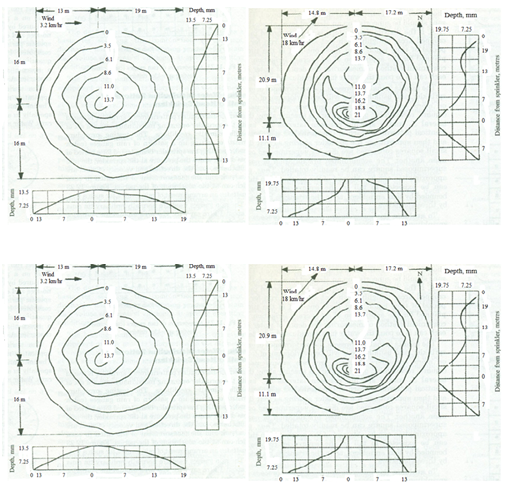
Fig. 40.1. Moisture distribution pattern from a rotating head sprinkler under favourable & windy conditions of pressure and wind.
(Source: Michael, 2010)
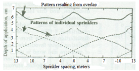
Fig. 40.2. Water distribution pattern from overlapped sprinklers.
(Source: Michael, 2010)
40.3 Uniformity of Coverage
Measuring Distributions: The distribution of sprinkler systems can be evaluated by measuring the patterns of individual sprinklers, and then by combining, as discussed in the previous section, or by sampling directly, ASAE Recommendations S330 (ASAE Yearbook, 1979) describes procedures for measuring the distribution of a single sprinkler including the format for presenting the data. According to ASAE measurements the test site should be nearly level and the minimum clean distance upwind should be positioned at least 60 cm above the collectors, and 90cm above the surface. Preferably, the sprinkler should be located in the center of the grid of the four adjacent central collectors. A minimum of 80 collectors should receive water during a test. Wind direction and total wind movement at the 4-m height should be recorded for interpretation of the data. The distribution of a typical sprinkler system can be evaluated with a grid of catch cans or collectors. The grid should be located over a length equal to at least the sprinkler spacing on the lateral and over a width at least equal to lateral spacing. For linear moving systems, one or two lines of measuring devices perpendicular to the travel path may be more practical and meaningful than a grid system.
Uniformity Coefficients (Cu): It is a measurable index of the degree of uniformity obtainable for any size sprinkler operating under given conditions. This uniformity coefficient is affected by the pressure nozzle size relations, sprinkler spacing and by wind conditions. The coefficient is computed from field observations of the depths of water collected in catch cans or collectors placed at regular intervals within a sprinkled area as per procedure described in preceding sections. It is expressed by the equation developed by Christiansen (1942):
![]() (40.1)
(40.1)
in which
Cu = coefficient of uniformity
m = average value of all observations (average application rate), mm
n = total number of observation points
X = numerical deviation of individual observation s from the average application rate, mm.
A uniformity coefficient of 100 per cent (obtained with overlapping sprinklers) is indicative of absolutely uniform application, whereas the water application is less uniform with a lower value of coefficient. A uniformity coefficient of 85 per cent or more is considered to be satisfactory.
Pattern Efficiency: The pattern efficiency (also known as distribution efficiency)is calculated with the total depths of water collected at each of the catch cans placed at the grid points. The minimum depth is calculated considering average of the lowest one fourth of the depths collected in catch cans used in a particular test. Pattern efficiency is given by
![]() (40.2)
(40.2)
The pattern efficiency is useful in calculating the average depth to be applied for a certain minimum depth. The pattern efficiency is influenced by the wind conditions.
The application efficiency is given by
![]() (40.3)
(40.3)
40.4 Operation and Maintenance
The operation mode for a solid-set or permanent sprinkler system depends upon the design and use of the system, available labor, water supply, and available capital. Either system can be designed on the lateral or area (block) design method. With the lateral design method, individual laterals are controlled by valves and each lateral may be operated as desired. Normally, more than one lateral is operated simultaneously, but the operating laterals usually are widely separated in the field. The lateral design method minimizes the main or supply line pipe size, but it increases the number of valves required and also the time to open and close valves when a manually operated valve system is used. With the area (or block) design method, a contiguous portion of the field is irrigated at one time. Usually a sub-main is installed to supply water to that portion of the field.
For frost and snow protection, the entire system may be operated at one time. Depending upon the crop being protected, the application rate will be 2 to 5 mm (0.08 to 0.18 in.) per hour. Both undertree and overtree systems are used; however with saline water only undertree systems should be used. Single nozzle, medium pressure sprinklers should be used for frost and snow protection. For crop cooling and blossom delay, the entire system may be sequenced in alternate on-off modes as one portion of the system may be operated at a time and the operation can be switched to another portion of the system, Sequencing is best accomplished with electric controllers and automatic valves. If the system is being used strictly for irrigation, only a portion of the system is normally operated at one time. Where several hours are required for irrigation, control may be manual or automatic.
A sprinkler system like any other farm equipment needs maintenance to keep it operating at peak efficiency. Parts of the system subject to wear are the rotating sprinkler heads, the pumping set, the couplers and the pipeline. General principle regarding the maintenance of the pipes and fittings and sprinkler heads are given below:
1. Pipes and Fittings: The pipes and fittings require virtually no maintenance but attention must be given to the following procedures:
(a) Occasionally clean any dirt or sand out of the groove in the coupler in which the rubber sealing ring fits. Any accumulation of dirt or sand will affect the performance of the rubber sealing ring.
(b) Keep all nuts and bolt tight.
(c) Do not lay pipes on new damp concrete or on piles of fertilizer. Do not lay fertilizer sacks on the pipe.
The pipes are automatically emptied and ready to be moved. When the pump is first started and before the pressure has built up in the system the seals may give a little leakage. With full pressure in the system the couplers and fittings will be effectively leak free. If however there is a leakage check the following:
(a) There is no accumulation of dirt or sand in the groove in the coupler in which the sealing ring fits. Clean out any dirt or sand and refit the sealing ring.
(b) The end of the pipe going inside the coupler is smooth clean and not distorted.
(c) In the case of fittings such as bends, tees and reducers ensure that the fitting has been properly connected into the coupler.
2. Sprinkler Heads: The sprinkler heads should be given the following attention.
(a) When moving the sprinkler lines make sure that the sprinklers are not damaged or pushed into the soil.
(b) Do not apply oil, grease or any lubricant to the sprinklers. They are water lubricated and using oil, grease or any other lubricant may stop them from working.
(c) Sprinkler usually have a sealed bearing and at the bottom of the bearing there are washers. Usually it is the washers that wear and not the more expensive metal parts. Check the washers for wear once a season or every six months this is especially important where water is sandy. Replace the washers if worn.
(d) After several seasons operation the swing arm spring may need tightening. This is done by pulling out the spring end at the top and rebending it. This will increase the spring tension. In general check all equipment at the end of the season and make any repairs and adjustment and order the spare parts immediately so that the equipment is in perfect condition to start in the next season.
Storage: The following points are to be observed while storing the sprinkler equipment during the off season:
(a) Remove the sprinklers and store in a cool dry place.
(b) Remove the rubber sealing rings from the couplers and fittings and store them in a cool, dark place.
(c) The pipes can be stored outdoors in which cases they should be placed in racks with one end higher than the other. Do not store pipes along with fertilizer.
(d) Disconnect the suction and delivery pipe work from the pump and pour in a small quantity of medium grade oil. Rotate the pump for a few minutes. Blank off the suction and delivery branches. This will prevent the pump from rusting. Grease the shaft.
(e) Protect the electric motor from the ingress of dust, dampness and rodents.
40.5 Common Troubles and Remedies in Operation of Sprinkler System
The following are the general guidelines to identify and remove the common troubles in the sprinkler systems:
1) Pump does not Prime or Delivers Water
i) The pump suction lift should be checked, if it is within the limits. If not lower the pump closer to the water.
ii) Check the suction pipeline and all connections for air leaks. All connections and flanges should be air tight.
iii) Check that the strainer on the foot valve is not blocked
iv) Check that the flap in the foot valve in free to open fully.
v) Check the pump gland (s) gently. If necessary repack the gland (s) using a thick grease to seal the gland satisfactorily.
vi) Check that the gate valve on the delivery pipe is fully closed during priming and opens fully when the pump is running.
vii) Check that the direction of rotation of the pump is correct.
2) Sprinklers do not Turn
i) Check pressure.
ii) Check that the nozzle is not blocked. Preferably unscrew the nozzle or use a small soft piece of wood to clear the blockage. Do not use a piece of wire or metal as this may damage the nozzle.
iii) Check that the sprinkler can usually be pushed down towards the riser pipes so that the water pressure flushes out the bearing. If the bearing is still stiff dismantle and then clean it. Do not use oil, grease or any lubricant.
iv) Check that the condition of washers at the bottom of the bearing and replace then if worn or damaged.
v) Check that the swing arm moves freely and that the spoon which moves into the water stream is not bent by comparing it with a sprinkler which is operating correctly. If it is bent then very carefully bend it back into position.
vi) Adjust the swing arm spring tension. Usually it should not be necessary to pull up the spring by more than about 6mm.
3) Leakage from Coupler or Fittings
The sealing rings in the couplers and fittings are usually designed to drain the water from the pipes when the pressure is turned off. This ensures that the pipes are automatically emptied and ready to be moved. When the pump is first started and before the pressure has built up in the system the seals may give a little leakage. With full pressure in the system the couplers and fittings will be effectively leak-free. If, however, there is a leakage, check the following:
i) There is no accumulation of dirt or sand in the groove of the coupler in which the sealing ring fits. Clean out any dirt or sand and refit the sealing ring.
ii) The end of the pipe going inside the coupler is smooth, clean and not distorted.
iii) In the case of fittings such as bends, tees and reducers ensure that the fitting has been properly connected into the coupler.
Example 1: Determine the uniformity coefficient, Pattern and application efficiencies from the following data obtained from a field test on a square plot bounded by four sprinklers:
Sprinkler (S) - 4.76 x 3.2 mm nozzles at 2.8 kg/cm3
Spacing- 16 m x 12 m
Wind- 5 km/hr from south-west
Humidity- 49 percent
Time of test- 2 hour
|
S |
9.4 |
8.1 |
7.1 |
S |
|
8.6 |
8.1 |
10.4 |
10.7 |
8.8 |
|
9.4 |
9.6 |
9.6 |
9.9 |
9.4 |
|
9.9 |
8.4 |
9.6 |
9.1 |
9.6 |
|
S |
8.4 |
7.1 |
7.3 |
S |
Note: S indicates location of sprinklers.
Solution:
|
Observation |
Frequency |
Application rate x frequency |
Numerical deviations |
Frequency x deviations |
|
10.7 |
1 |
10.7 |
1.6 |
1.6 |
|
10.4 |
1 |
10.4 |
1.3 |
1.3 |
|
9.9 |
2 |
19.8 |
0.8 |
1.6 |
|
9.6 |
4 |
38.4 |
0.5 |
2 |
|
9.4 |
3 |
28.2 |
0.3 |
0.9 |
|
9.1 |
1 |
9.1 |
0 |
0 |
|
8.8 |
1 |
8.8 |
0.3 |
0.3 |
|
8.6 |
1 |
8.6 |
0.5 |
0.5 |
|
8.4 |
2 |
16.8 |
0.7 |
1.4 |
|
8.1 |
2 |
16.2 |
1 |
2 |
|
7.3 |
1 |
7.3 |
1.8 |
1.8 |
|
7.1 |
2 |
14.2 |
2 |
4 |
|
|
21 |
188.5 |
|
ΣX=17.4 |
Mean = = 8.97
Cu= 100
= 100
Total catch in 21 locations=188.5 mm in 2 hours
Average catch (188.5/21) = 8.97
Average of the lowest one fourth of the cans (5 out of 21)
= (37.7/5)=7.54 mm or 3.77 mm/hr
Pattern efficiency = (7.54/8.97) *100= 84 percent
Average rate applied =
= 0.45 cm/hr
Application efficiency = (0.377/0.56) x 100= 83.77 percent
References
Christiansen, J.E. (1942). Irrigation by sprinkling. California Agriculture Experiment Station Bulletin 670. Berkeley, California, United States of America, University of California.
Michael, A. M. (2010). Irrigation Theory and Practice, Vikas Publishing House PVT Ltd, Delhi, India: 590.
Suggested Reading
Majumdar, Kumar. Dilip. (2004). Irrigation Water Management, Prentice Hall Inc., New Delhi, India: 206,207,208.
Heermann, D.F. and Kohl, R.A. (1980). Fluid Dynamics of Sprinkler systems. (Chapter 14 in Design and Operation of Farm Irrigation systems edited by Jensen, M.E.) ASAE Monograph 3. St. Joseph, MI.
Last modified: Friday, 14 March 2014, 4:24 AM