Site pages
Current course
Participants
General
Module 1:Water Resources Utilization& Irrigati...
Module 2:Measurement of Irrigation Water
Module 3: Irrigation Water Conveyance Systems
Module 4: Land Grading Survey and Design
Module 5: Soil –Water – Atmosphere Plants Intera...
Module 6: Surface Irrigation Methods
Module 7: Pressurized Irrigation
Module 8: Economic Evaluation of Irrigation Projec...
Topic 9
LESSON 39 Application of Fertilizers and Chemicals through Sprinkler System
Sprinkler systems are also used to apply should fertilizers, herbicides, and pesticides along with water. The process of applying fertilizers along with water through pressurized irrigation system is known as the fertigation. The process of applying all types of soluble chemicals including fertilizers along with water through the pressurized irrigation system is known as chemigation. The commonly used to inject chemicals and fertilizers through a sprinkler system devices are: Pressurized tank, venture system and pump.
39.1. Advantages of Fertigation / Chemigation
- The fertigation/chemigation facilitates frequent application of fertilizers and chemicals to the crop in an amount as per the need of the crops during a specified crop growth stage and conditions.
- There is controlled application of fertilizers and chemicals along with water and hence if the uniformity in application of water is high the, efficiency of application of fertilizers and chemicals will also be high.
- There is less wastage of fertilizers and chemicals therefore saving the expensive commodity.
- Due to efficient application, the crop yield also increases.
- As there is controlled application, the leaching of the fertilizers and chemicals is minimized, reducing the groundwater pollution and environmental hazards.
39.2 General Points Consideration for Fertigation
- The following points should be considered in operation of fertigation/chemigation system.
- The fertilizers/chemicals to be used should be water soluble.
- The fertilizers/chemicals should be injected at the upstream end of the filters to ensure that any undissolved particles of the fertilizers/chemicals are removed before entering in to the system.
- The irrigation system should be pressurized before starting the process of fertigation and chemigation.
- The system should be equipped with the anti-siphon device to protect the water supply from contamination of the fertilizers/chemicals. For this purpose, it is important to provide check and vacuum relief valves (anti-siphon devices) for preventing the chemical from draining or siphoning back into the irrigation well or to other water supply source. The vacuum and check valves must be located between the pump and the point of chemical injection. If water is blend from the main irrigation supply into the chemical supply tank, the connecting line too must be equipped with a check valve to prevent the supply tank from overflowing and contaminating the adjacent area with chemical solution.
- The coefficient of uniformity (CU) of water application of irrigation system should be between 80 to 90%. This is use to ensure uniform application of the chemicals to the area that is being fertilized or treated with herbicides or pesticides. Non uniform systems would results in poor placement of the chemicals.
- The size of the pump or rate of chemical injection into the sprinkler system should be checked closely so as to ensure desired application rate of the chemical. The rate of injection also depends on requirement: a) for continuous injection b) the entire volume of chemical is injected in the beginning or at the end of the irrigation set. Intermittent injection requires the system to be flushed intermittently.
39.3 Fertigation / Chemigation Devices
There are several equipments available for the application of fertilsers/chemicals through the sprinkler irrigation systems. The choice of a particular method depends on: flow rate, operating pressure, type of fertilizers/chemicals to be used, concentration of the fertilsers/chemicals, time of operation and power source.
The selected equipment should be able to satisfy the following requirements.
-
Desired rate of application
-
Desired duration of application
-
Desire proportion of fertilizers
-
Staring and completion time
-
Normally the concentration of the fertilizers is in the range of 200 to 500 ppm and that for bactericides it is in the 0.5 to 10 ppm
39.3.1 Pressurized Tank
A pressure differential is created by throttling the water flow in the control head and diverting a fraction of the water through a tank containing the fertilizer solution. Fig.39.1 shows a fertilizer used for sprinkler and micro irrigation system. A gradient of 0.1 to 0.2 bar (1 – 2 m) is required to redirect an adequate stream of water through a connecting tube of 9 – 12 mm diameter. The pressurized tank is generally, made of corrosion resistant enamel-coated or galvanized cast iron, stainless steel or fiberglass. This should withstand the network working pressure. The diverted water is mixed with solid soluble or liquid fertilizers in the pressure tank. Once the solid fertilizer had been fully dissolved, continuous dilution by water gradually decreases the concentration of the chemical solution. The tank should have enough capacity to store the required quantity. This device is cheap and simple to use. A wide dilution ratio can be attained without external source of energy.
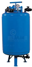
Fig. 39.1. Fertilizer tank.
(Source: http://www.jains.com/Fertigation/fertilizer%20tank.htm)
Limitations: Nutrient/Chemical concentration in the irrigation water cannot be precisely regulated. Prior to each application, the tank has to be refilled with fertilizer. Valve throttling generates pressure losses, and the system cannot be straight forwardly automated.
39.3.2 Venturi Injector
The fertilizer solution is injected in to the system by suction generated by water making water-to flow through a constricted passageway called venturi. The high flow velocity of water in the constriction reduces water pressure below the atmospheric pressure, so that the vacuum is created and fertilizer solution is sucked from an open tank into the constriction through a small diameter tube. Fig. 39.2 shows a venturi injector used for chemicals and fertilizer injection.

Fig. 39.2. Venturi injector. (Source: http://www.netafimusa.com)
Venturi is made of corrosion-resistant materials such as copper, brass, plastic and stainless steel. Venturi devices require excess pressure to allow for the necessary pressure loss. Maintaining a constant pressure in the irrigation system guarantees uniform long-term nutrient concentration. Common head losses are above 33% of the inlet pressure. Double stage ventury injectors have lower pressure loss and pipe diameter. It can be adjusted by valves and regulators, suction rates vary from 0.1 to 2000 . Venturi injectors are installed on the line or on a bypass. The injection rate depends upon the pressure loss, which ranges from 10% to 75% of the system’s pressure and is controlled by the injector type and operating conditions. The injection rate can be controlled by
-
Changing the flow through the venture injector
-
Controlling the system operating pressure
-
Adjusting the control valve at discharge side
-
Using the metering valve
Advantages: Cheap open tanks may be used for storing the fertilizers/chemical. A wide range of suction rates can be created by changing the diameter of the venturi dimensions of converging and diverging sides; and valves. It has simple operation and low wear. It requires easy installation and mobility. It is compatible with automation. It provides uniform nutrient concentration.
Limitations: There is a significant pressure loss. The injection rates are affected by pressure fluctuations.
39.3.3 Injection Pumps
Hydraulic Pumps: These are versatile, reliable feature low operation and maintenance costs. A diaphragm or piston movement injects the fertilizer solution into the irrigation system. Water-driven diaphragm and piston pump combine precision, reliability and low maintenance costs. Fig. 39.3 shows piston and diaphragm pump.
Hydraulic pump used in fertigation can be automated. A pulse transmitter is mounted on the pump. The movement of the piston or diaphragm spoke sends electrical signals to the controller that measures the delivered volume. Measurement can also be performed by small fertilizer-meters installed on the injection tube. The controller allocates fertilizer solution according to a preset program.
In glasshouses, simultaneous application of a multi-nutrient solution is routine practice. When the distinct chemical compounds in the fertilizers are incompatible and cannot be combined in a concentrated solution due to the risk of decomposition or precipitation, two or three injectors are installed inline one after another, in the control head. The application ratio between the injectors is coordinated by the irrigation controller. In high valve crops grown in glasshouses on detached media, the irrigation water is mixed with fertilizers in a mixing chamber (mixer).
Electric Pump: Electric pumps are inexpensive and reliable (Fig.39.4). Operation costs are low. They can be readily integrated into automatic systems. A wide selection of pump is available from small low-capacity to massive high-capacity pumps. The injection pressure is the range of 1 – 10 bars. Electric piston pumps are exceptionally precise and appropriate for accurate mixing in constant proportions of several stock solutions.
Variable speed motors and variable stroke length allow for a wide range of dosing from 0.5 to 300 Lh-1 at the working pressure of 2 – 10 bars.
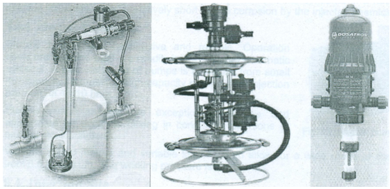
Fig. 39.3. Piston (left) and diaphragm (right) hydraulic pumps and no – drain hydraulic pump. (Source: http://www.amiad.com/products.asp)
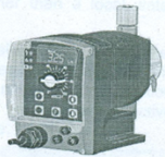
Fig. 39.4. Electric pump. (Source: http://www.amiad.com/products.asp)
39.4 Dosing Patterns
Normally two types of dosing are practiced for chemicals and fertilizers injection. These are: i) quantitative and ii) proportional dosing.
I) Quantitative Dosing: A measured amount of fertilizer is injected into the irrigation system during each water application. Injection may be initiated and controlled automatically or manually.
Ii) Proportional Dosing: It maintains a constant predetermined ratio between the irrigation water and the fertilizer solution. Pumps inject the fertilizer solution in a pulsating pattern. Venturi injectors apply the fertilizer continuously and in constant concentration.
39.5 Prevention and Precautions
Avoiding Corrosion Damage: Most fertilizer solutions are corrosive. Accessories exposed to the injected solution should be corrosion-resistant. The injection device and irrigation system must be thoroughly flushed after fertilizer injection.
Backflow Prevention: Whenever the irrigation system is connected to a potable water supply network, strict precautions should be taken to avoid backflow of fertilizer containing irrigation water. Fig. 39.5 shows back flow prevention valves.
Back – siphonage: Back siphonage occurs when low pressure in the supply line is created by an excessive hydraulic gradient in undersized pipes in the supply line. A break in the supply line, pump or power failure occurs.
Back – Pressure: It occurs when the pressure in the irrigation system is higher than in the water supply network. This happens when booster pumps are used for irrigation or when the area under irrigation is topographically higher than a local water supply tank.
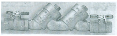
Fig. 39.5. Tedem backflow preventer.
(Source: http://www.amiad.com/products.asp)
An atmospheric vacuum breaker installed beyond the last valve allows air to enter downstream when pressure falls. A pressure vacuum breaker has an atmospheric vent valve that is internally loaded by a spring. This valve is unsuitable for fertigation system and it is operated by an external source of energy. Vacuum breakers are effective only against back– siphonage and do not prevent back-pressure.
Location of Fertigation Device: The fertigation devices should be installed between the sand filter, (if installed) and the screen or disc filter. It is essential that the fertigation devices be installed at the upstream end of the screen or disc filters to prevent any impurities in the fertilser/chemical solution from entering the irrigation system.
39.6 Fertilizer Quantity Computation
The quantity of fertilizer to be injected in the system is calculated using the following formula given by Michael (2010).
![]()
in which,
WF= amount of fertilizer required in per setting, kg
Ds= distance between sprinklers, m
Dl= distance between laterals, m
Ns= number of sprinklers, and
Qf= recommended fertilizer dose, kg/ha
Example 39.1: A sprinkler system is used apply fertilizer at the recommended dose of 60 kg/h at each setting. The sprinkler laterals are spaced at 20 m on the main line. Ten sprinklers are attached in a lateral and these are spaced at 12 m apart. Determine the amount of fertilizer to be applied in each setting.
Solution:
Ds = 12 m, = 20 m, Ns = 14 and Qf = 60 kg/ha
![]()
= 14.4 kg
References
http://www.jains.com/Fertigation/fertilizer%20tank.htm
http://www.netafimusa.com
http://www.amiad.com/products.asp
Michael, A. M. (2010). Irrigation Theory and Practice, Vikas Publishing House Pvt. Ltd, Delhi, India.
Suggested Reading
Heermann, D.F. and Kohl, R.A. (1980). Fluid Dynamics of Sprinkler systems. (In Design and Operation of Farm Irrigation Systems, Chapter 14, edited by Jenson, M.E.) ASAE Monograph 3. St. Joseph, MI.
James, Larry G. (1988). Principles of Farm Irrigation System Design, John Wiley and Sons, Inc., New York: 180.
39.1. Advantages of Fertigation / Chemigation
i) The fertigation/chemigation facilitates frequent application of fertilizers and chemicals to the crop in an amount as per the need of the crops during a specified crop growth stage and conditions.
ii) There is controlled application of fertilizers and chemicals along with water and hence if the uniformity in application of water is high the, efficiency of application of fertilizers and chemicals will also be high.
iii) There is less wastage of fertilizers and chemicals therefore saving the expensive commodity.
iv) Due to efficient application, the crop yield also increases.
v) As there is controlled application, the leaching of the fertilizers and chemicals is minimized, reducing the groundwater pollution and environmental hazards.
39.2 General Points Consideration for Fertigation
The following points should be considered in operation of fertigation/chemigation system.
i) The fertilizers/chemicals to be used should be water soluble.
ii) The fertilizers/chemicals should be injected at the upstream end of the filters to ensure that any undissolved particles of the fertilizers/chemicals are removed before entering in to the system.
iii) The irrigation system should be pressurized before starting the process of fertigation and chemigation.
iv) The system should be equipped with the anti-siphon device to protect the water supply from contamination of the fertilizers/chemicals. For this purpose, it is important to provide check and vacuum relief valves (anti-siphon devices) for preventing the chemical from draining or siphoning back into the irrigation well or to other water supply source. The vacuum and check valves must be located between the pump and the point of chemical injection. If water is blend from the main irrigation supply into the chemical supply tank, the connecting line too must be equipped with a check valve to prevent the supply tank from overflowing and contaminating the adjacent area with chemical solution.
v) The coefficient of uniformity (CU) of water application of irrigation system should be between 80 to 90%. This is use to ensure uniform application of the chemicals to the area that is being fertilized or treated with herbicides or pesticides. Non uniform systems would results in poor placement of the chemicals.
vi) The size of the pump or rate of chemical injection into the sprinkler system should be checked closely so as to ensure desired application rate of the chemical. The rate of injection also depends on requirement: a) for continuous injection b) the entire volume of chemical is injected in the beginning or at the end of the irrigation set. Intermittent injection requires the system to be flushed intermittently.
39.3 Fertigation / Chemigation Devices
There are several equipments available for the application of fertilsers/chemicals through the sprinkler irrigation systems. The choice of a particular method depends on: flow rate, operating pressure, type of fertilizers/chemicals to be used, concentration of the fertilsers/chemicals, time of operation and power source.
The selected equipment should be able to satisfy the following requirements.
· Desired rate of application
· Desired duration of application
· Desire proportion of fertilizers
· Staring and completion time
· Normally the concentration of the fertilizers is in the range of 200 to 500 ppm and that for bactericides it is in the 0.5 to 10 ppm
39.3.1 Pressurized Tank
A pressure differential is created by throttling the water flow in the control head and diverting a fraction of the water through a tank containing the fertilizer solution. Fig.39.1 shows a fertilizer used for sprinkler and micro irrigation system. A gradient of 0.1 to 0.2 bar (1 – 2 m) is required to redirect an adequate stream of water through a connecting tube of 9 – 12 mm diameter. The pressurized tank is generally, made of corrosion resistant enamel-coated or galvanized cast iron, stainless steel or fiberglass. This should withstand the network working pressure. The diverted water is mixed with solid soluble or liquid fertilizers in the pressure tank. Once the solid fertilizer had been fully dissolved, continuous dilution by water gradually decreases the concentration of the chemical solution. The tank should have enough capacity to store the required quantity. This device is cheap and simple to use. A wide dilution ratio can be attained without external source of energy.

Fig. 39.1. Fertilizer tank.
(Source: http://www.jains.com/Fertigation/fertilizer%20tank.htm)
Limitations: Nutrient/Chemical concentration in the irrigation water cannot be precisely regulated. Prior to each application, the tank has to be refilled with fertilizer. Valve throttling generates pressure losses, and the system cannot be straight forwardly automated.
39.3.2 Venturi Injector
The fertilizer solution is injected in to the system by suction generated by water making water-to flow through a constricted passageway called venturi. The high flow velocity of water in the constriction reduces water pressure below the atmospheric pressure, so that the vacuum is created and fertilizer solution is sucked from an open tank into the constriction through a small diameter tube. Fig. 39.2 shows a venturi injector used for chemicals and fertilizer injection.

Fig. 39.2. Venturi injector. (Source: http://www.netafimusa.com)
Venturi is made of corrosion-resistant materials such as copper, brass, plastic and stainless steel. Venturi devices require excess pressure to allow for the necessary pressure loss. Maintaining a constant pressure in the irrigation system guarantees uniform long-term nutrient concentration. Common head losses are above 33% of the inlet pressure. Double stage ventury injectors have lower pressure loss and pipe diameter. It can be adjusted by valves and regulators, suction rates vary from 0.1 ![]() to 2000
to 2000 ![]() . Venturi injectors are installed on the line or on a bypass. The injection rate depends upon the pressure loss, which ranges from 10% to 75% of the system’s pressure and is controlled by the injector type and operating conditions. The injection rate can be controlled by
. Venturi injectors are installed on the line or on a bypass. The injection rate depends upon the pressure loss, which ranges from 10% to 75% of the system’s pressure and is controlled by the injector type and operating conditions. The injection rate can be controlled by
· Changing the flow through the venture injector
· Controlling the system operating pressure
· Adjusting the control valve at discharge side
· Using the metering valve
Advantages: Cheap open tanks may be used for storing the fertilizers/chemical. A wide range of suction rates can be created by changing the diameter of the venturi dimensions of converging and diverging sides; and valves. It has simple operation and low wear. It requires easy installation and mobility. It is compatible with automation. It provides uniform nutrient concentration.
Limitations: There is a significant pressure loss. The injection rates are affected by pressure fluctuations.
39.3.3 Injection Pumps
Hydraulic Pumps: These are versatile, reliable feature low operation and maintenance costs. A diaphragm or piston movement injects the fertilizer solution into the irrigation system. Water-driven diaphragm and piston pump combine precision, reliability and low maintenance costs. Fig. 39.3 shows piston and diaphragm pump.
Hydraulic pump used in fertigation can be automated. A pulse transmitter is mounted on the pump. The movement of the piston or diaphragm spoke sends electrical signals to the controller that measures the delivered volume. Measurement can also be performed by small fertilizer-meters installed on the injection tube. The controller allocates fertilizer solution according to a preset program.
In glasshouses, simultaneous application of a multi-nutrient solution is routine practice. When the distinct chemical compounds in the fertilizers are incompatible and cannot be combined in a concentrated solution due to the risk of decomposition or precipitation, two or three injectors are installed inline one after another, in the control head. The application ratio between the injectors is coordinated by the irrigation controller. In high valve crops grown in glasshouses on detached media, the irrigation water is mixed with fertilizers in a mixing chamber (mixer).
Electric Pump: Electric pumps are inexpensive and reliable (Fig.39.4). Operation costs are low. They can be readily integrated into automatic systems. A wide selection of pump is available from small low-capacity to massive high-capacity pumps. The injection pressure is the range of 1 – 10 bars. Electric piston pumps are exceptionally precise and appropriate for accurate mixing in constant proportions of several stock solutions.
Variable speed motors and variable stroke length allow for a wide range of dosing from 0.5 to 300 Lh-1 at the working pressure of 2 – 10 bars.

Fig. 39.3. Piston (left) and diaphragm (right) hydraulic pumps and no – drain hydraulic pump. (Source: http://www.amiad.com/products.asp)

Fig. 39.4. Electric pump. (Source: http://www.amiad.com/products.asp)
39.4 Dosing Patterns
Normally two types of dosing are practiced for chemicals and fertilizers injection. These are: i) quantitative and ii) proportional dosing.
I) Quantitative Dosing: A measured amount of fertilizer is injected into the irrigation system during each water application. Injection may be initiated and controlled automatically or manually.
Ii) Proportional Dosing: It maintains a constant predetermined ratio between the irrigation water and the fertilizer solution. Pumps inject the fertilizer solution in a pulsating pattern. Venturi injectors apply the fertilizer continuously and in constant concentration.
39.5 Prevention and Precautions
Avoiding Corrosion Damage: Most fertilizer solutions are corrosive. Accessories exposed to the injected solution should be corrosion-resistant. The injection device and irrigation system must be thoroughly flushed after fertilizer injection.
Backflow Prevention: Whenever the irrigation system is connected to a potable water supply network, strict precautions should be taken to avoid backflow of fertilizer containing irrigation water. Fig. 39.5 shows back flow prevention valves.
Back – siphonage: Back siphonage occurs when low pressure in the supply line is created by an excessive hydraulic gradient in undersized pipes in the supply line. A break in the supply line, pump or power failure occurs.
Back – Pressure: It occurs when the pressure in the irrigation system is higher than in the water supply network. This happens when booster pumps are used for irrigation or when the area under irrigation is topographically higher than a local water supply tank.

Fig. 39.5. Tedem backflow preventer.
(Source: http://www.amiad.com/products.asp)
An atmospheric vacuum breaker installed beyond the last valve allows air to enter downstream when pressure falls. A pressure vacuum breaker has an atmospheric vent valve that is internally loaded by a spring. This valve is unsuitable for fertigation system and it is operated by an external source of energy. Vacuum breakers are effective only against back– siphonage and do not prevent back-pressure.
Location of Fertigation Device: The fertigation devices should be installed between the sand filter, (if installed) and the screen or disc filter. It is essential that the fertigation devices be installed at the upstream end of the screen or disc filters to prevent any impurities in the fertilser/chemical solution from entering the irrigation system.
39.6 Fertilizer Quantity Computation
The quantity of fertilizer to be injected in the system is calculated using the following formula given by Michael (2010).
![]()
in which,
![]() = amount of fertilizer required in per setting, kg
= amount of fertilizer required in per setting, kg
![]() = distance between sprinklers, m
= distance between sprinklers, m
![]() = distance between laterals, m
= distance between laterals, m
![]() number of sprinklers, and
number of sprinklers, and
![]() = recommended fertilizer dose, kg/ha
= recommended fertilizer dose, kg/ha
Example 39.1: A sprinkler system is used apply fertilizer at the recommended dose of 60 kg/h at each setting. The sprinkler laterals are spaced at 20 m on the main line. Ten sprinklers are attached in a lateral and these are spaced at 12 m apart. Determine the amount of fertilizer to be applied in each setting.
Solution:
Ds = 12 m, ![]() = 20 m, Ns = 14 and Qf = 60 kg/ha
= 20 m, Ns = 14 and Qf = 60 kg/ha
![]()
= 14.4 kg
References
http://www.jains.com/Fertigation/fertilizer%20tank.htm
http://www.netafimusa.com
http://www.amiad.com/products.asp
Michael, A. M. (2010). Irrigation Theory and Practice, Vikas Publishing House Pvt. Ltd, Delhi, India.
Suggested Reading
Heermann, D.F. and Kohl, R.A. (1980). Fluid Dynamics of Sprinkler systems. (In Design and Operation of Farm Irrigation Systems, Chapter 14, edited by Jenson, M.E.) ASAE Monograph 3. St. Joseph, MI.
James, Larry G. (1988). Principles of Farm Irrigation System Design, John Wiley and Sons, Inc., New York: 180.
Last modified: Saturday, 15 March 2014, 11:36 AM