Site pages
Current course
Participants
General
Module 1:Water Resources Utilization& Irrigati...
Module 2:Measurement of Irrigation Water
Module 3: Irrigation Water Conveyance Systems
Module 4: Land Grading Survey and Design
Module 5: Soil –Water – Atmosphere Plants Intera...
Module 6: Surface Irrigation Methods
Module 7: Pressurized Irrigation
Module 8: Economic Evaluation of Irrigation Projec...
Topic 9
LESSON 42 Components of Drip Irrigation System-I
42.1 Introduction
Drip irrigation system applies water in low volumes uniformly along with the fertilizers onto or into the soil near the plant root zone. This involves several components. These are the network of pipes (main line, sub mains, laterals), emitting device called as drippers or emitters, control head consisting of pumps, filters and fertigation units; and other accessories such as valves, gages etc. The main line delivers water from water source with the help of pumping device or elevated water tank to the sub main and the sub mains to the laterals. The emitters which are attached to the laterals deliver water onto or into the soil for irrigation. Emitters are the end device of the drip irrigation system. The typical layout of the drip irrigation system with its components is shown in Figs. 42.1 and Fig 42.2. These figures show arrangement of pipe network (main, sub-main, lateral) and layout of drip irrigation system in the field.
The components of the drip irrigation system are classified into following principal categories:
a) Pump and prime mover: The pressure necessary to force water through the components of the system including fertilizer tank, filter unit, mainline, sub main, laterals and provide at the emitters at the desired pressure is obtained by a pump of suitable capacity or the overhead water tank located at suitable elevation.
b) Water source: Water sources such as river, lake, reservoir/tank, well, canal water supply or connection to a public commercial or cooperative water supply network can be used. Drip irrigation is a pressurized irrigation technology in which water is delivered from these sources by increasing its internal energy (pressure) by pumping.
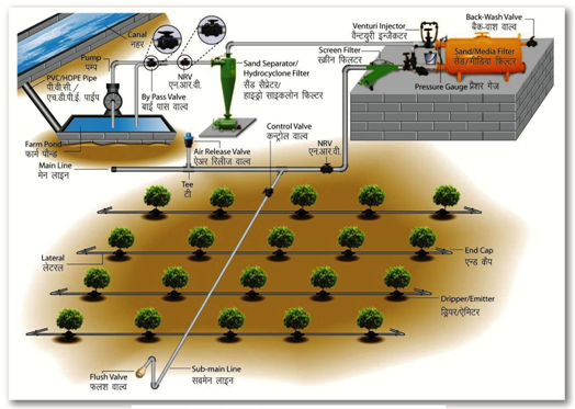
Fig. 42.1. Component and layout of drip irrigation system.
(Source:http://74.52.53.155/sites/all/themes/ncpah/images/Drip_irrigation.jpg)
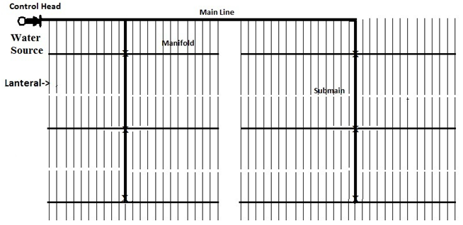
Fig. 42.2. Typical layout of drip irrigation system.
c) Pipe network: Mainline, submains and manifolds (feeder pipes) and laterals.
d) Emitting devices: Emitters or drippers or the laterals integrated with drippers/emitters and line source with drippers.
e) Control devices: Valves, flow meters, pressure and flow regulators, automation equipment, backflow preventers, vacuum and air release valves, etc.
f) Filtration devices: Removal of suspended materials in the water. Media, screen and disc filters.
g) Chemical injectors: For application of plant nutrients and water treatment agents along with the irrigation water. Pressurized tank, venture injector, injection pump.
42.2 The Source
There are two alternative sources of water supply:
a) Direct withdrawal from surface source (such as a river, stream, pond or dam reservoir) or from an underground sources (such as a well). The pumping devices need to be installed for the withdrawal.
b) Connection to a commercial, public or co-operative supply network. If pumping is needed, the pump will be chosen according to the required flow rate and pressure in the irrigation system. When connected to a water supply network, the diameter of the connection, main valve and the delivering line should correspond with the planned flow rate and working pressure in the irrigated area.
42.3 The Pumping Devices
The pumping devices are required to provide the pressure to pass water through the control head, different accessories and pipe network and then to the emitting devices at desired pressure. The pressure can be developed by using the elevated tanks or pumps. The elevated tanks can provide the pressure to the small system with micro tubes as the emitting devices. Other systems need the pumps. The pumps to be used may be centrifugal pump, submersible pump, turbine pumps. They may be powered by the electric motor or the diesel pump.
42.4 The Pipe Network
42.4.1 Main
Pipes of mainlines are usually made of poly vinyl chloride (PVC) or high density polyethylene (HDPE). Ordinary PVC pipes have not UV protection and should be installed underground. Recently, unplasticized PVC (uPVC) pipes are manufactured with reduced sensitivity to ultra-violate (UV) rays and better endurance than ordinary PVC pipes. HDPE pipes can be installed inside or above ground, as they are impregnated with carbon black that provides protection against UV. The nominal working pressure of pipes has to be higher than that of the submain/drip laterals. The pipes of diameter 50 mm or above and the pressure rating of more than 4 kg/cm2 are used for mainline. The exact diameter and pressure ratings are decided in the process of design and depend on the size of the area irrigated, emitter operating pressure, topography, static and delivery heads etc.
42.4.2 Submains
Submains are installed underground (PVC or HDPE) or above ground (HDPE only.) The pipes of diameter 32 mm or above and the pressure rating of more than 2.5 kg/cm2 are used for sub mainline
42.4.3 Manifolds
In certain circumstances, when rows are very long or in rolling topography, sub-division of the plot by submains is insufficient. In these cases secondary partition is carried out by manifolds. Manifolds are used also to simplify operation and to lower accessories costs.
42.4.4 Laterals
Laterals are the tubes on which the emitters are mounted or within which they are integrated. They are usually made of low density polythene (LDPE) or linear low density polythene (LLDPE) (Fig. 42.3) with features such as flexibility, non corrosivety, resistance to solar radiation and temperature fluctuation and generally black in color. Laterals usually have inner diameters in the range of 12 to 20 mm with wall thickness varying from 1 to 3 mm. The wall thickness is made to withstand pressure more than 2 kg/cm2 depending on the requirement. The laterals may be laid on the soil surface or underground. Laterals buried at 5-10 cm below soil surface is suitable to vegetables grown on hillocks or under plastic mulch. Laterals need to distribute the water uniformly along their length by means of drippers or emitters.

Fig. 42.3. Laterals pipe. (Source:http://74.52.53.155/sites/all/themes/ncpah/images/Drip_irrigation.jpg)
42.5 Control and Monitoring Devices
42.5.1 Valves
Flow and pressure control valves are required for controlling water distribution and regulating pressure in the pipeline. The valves used in drip irrigation systems include air release and vacuum relief valve, pressure regulating valves, flow regulation valves, non return valves and on hyphen and hyphen off valves.
- Manual or Automatic Flow Regulating Valves: Manual or automatic valves are used for the opening and shutdown of water and for splitting the irrigated area into subunits.
- Pressure Regulators or Pressure Relief Valves: These are used to prevent excessive pressure beyond the working pressure of the system. These are installed at any point where there is a possibility of existing excessively high pressure. Such kind of high pressure may be generated in the system from sudden opening and closing of the valves, starting and stopping of a pump.
Closing and opening of the flow regulating valves gradually and using the air vents/relief valves at the proper location may prevent to generate the excessive pressure in the system. By pass assembly to bypass the excess water and pressure right at the source and pump could be adequate instead of pressure regulators or pressure relief valves.
- Check Valves and Backflow Preventers: Check valves and backflow preventers are required when fertilizers or other chemicals are injected into the irrigation system, if the irrigation system is connected to potable water supply network.
- Air-Release/Relief Valves: Air-release/relief valves are installed at the higher elevation points of the system to prevent air flow in the pipes. These valves allow air to escape when filling pipelines with water and remove air pockets at high points in the system. High air content in the pipes may interfere with water flow, increase friction with pipe walls, distort water measurement and may cause water hammer and pipe burst.
- Vacuum Breakers: Vacuum breakers prevent the collapse of pipes in steep slopes and drip laterals in sub-surface drip irrigation (SDI) systems. In SDI they also eliminate the suction of soil particles into the drippers after shutdown of the water supply. Vacuum relief valves, which have orifices of size 25 to 200 mm in diameter, are designed to exhaust large volume of air during pipe filling and to close when the filling stops.
42.5.2 Gages
Pressure gauges monitor water pressure in the system and ensure operating pressure remains close to the recommended or desired values. Based on where the pressure gauge is installed, it will measure water pressure in a various ranges, from 0 to 10 kg/cm2 near the pump to 0-2 kg/cm2 at the end of drip lateral. Pressure gauges may be installed at set points (near the pump, before and after the filter, near the field). They can also be mounted as portable devices and installed temporarily at the end of a drip lateral.
42.5.3 Water Meters
Water meters monitor and record the amount of water moving through a pipe where the water meter is installed. When a stopwatch is used together with a water meter, it is possible to determine the discharge in the system.
42.6 Control Head
The main components of the control head are the filtration and chemigation units.
44.6.1 Filtration Systems
Filtration is the key to the success or failure of a drip irrigation system. The narrow water passage or pathways in the emitters of the drip irrigation system are susceptible to clogging by suspended matter and chemicals that precipitate from the irrigation water. The clogging of the emitters can be partial or full causing the reduction in the emission uniformity and rated discharge of the emitters. Clogging can be prevented or reduced by:
a) Preliminary separation of suspended solid particles by settling ponds, settling tanks and sand separators.
b) Complimentary chemical treatments for decomposition of suspended organic matter; to hinder the development of slime by microorganisms; to prevent chemical precipitates deposition and to dissolve previous deposited precipitates.
c) Filtration of the irrigation water: The media filters usually called as sand filters, screen filters or disc filters are used.
Filtration devices are usually installed at the control head. If the irrigation water is heavily contaminated, secondary control filters are installed at the subunit valves. Filters should be flushed and cleaned routinely. Flushing can be done manually or automatically. The filters can be installed in arrays of two or more units. The installation of the filters causes the additional head loss in the system and need to be considered while designing the system. The details of the filters are explained in the next lesson.
42.6.2 Chemical Injectors
Three categories of chemicals viz. fertilizers, pesticides and anti-clogging agents need to be injected into irrigation systems depending on the need.
i) Fertilizers are the most commonly injected chemicals. In drip irrigation system, it is possible to time the application of the fertilizers as per the requirement of crop growth stages. The fertilizers need to be water soluble.
ii) Systemic pesticides are injected into drip irrigation systems to control insects and protect plants from a variety of diseases.
iii) Chemicals that clean drippers or prevent dripper clogging: Chlorine is used to kill algae and different microorganisms and to decompose organic matter, while acids are used to reduce water pH and dissolve precipitates.
42.7 Emitters
Emitters, the core of micro irrigation system or made of plastic material. The design of production of high quality drippers is comprised of delicate and complicated process. Water passes through the emitters and need to be delivered at constant and low with the desired uniformity. The emitters are designed to dissipate pressure and yield low discharge which does not vary significantly because of minor differences in pressure head.
42.7.1 Requirements of Good Emitters
Emitters, being the heart of the drip system and the success of the system being dependent on the operation of the emitters, need to satisfy the following requirements (Karmeli and Keller, 1974).
- Give a relatively low but uniform and constant discharge, which does not vary significantly because of minor differences in pressure.
- Have a relatively large section in order to reduce clogging problem.
- Be in expensive and compact as emitters constitute more than 1/3rd cost of the system.
42.7.2 Classification of the Emitters
Emitters can be classified on the basis of various characteristics (Karmeli and Keller, 1974). These are:
- Flow regime
- Pressure dissipation
- Operating pressure
- Discharge
- Lateral connection
- Water distribution
- Flow cross section
- Cleaning characteristics
- Pressure compensation
- Material used for production
Different types of emitters are shown in Figs. 42.4 and 42.5.

Fig. 42.4. Online pressure compensating drippers. (Source: Report of the Task Force on Micro-Irrigation, Ministry of Agriculture, Department of Agriculture & Cooperation, Govt. of India, New Delhi, Jan, 2004).
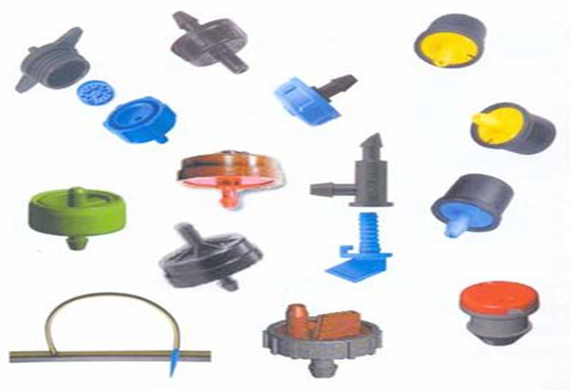
Fig. 42.5. Online non-pressure compensating drippers. (Source: Report of the Task Force on Micro-Irrigation, Ministry of Agriculture, Department of Agriculture & Cooperation, Govt. of India, New Delhi, Jan, 2004).
- Flow Regime: The three main regimes into which the emitters are classified are: laminar flow, partially turbulent flow and fully turbulent flow. Laminar flow regimes exist in the emitters having long flow path and low discharges, where as partially turbulent and turbulent flow exist in long path and multi exit emitters with relatively high discharges and in nozzle or vortex type emitters.
- Pressure Dissipation: Pressure dissipation is one of the important charectarsitc of the good emitters. Different forms of dissipation are used and accordingly the emitters are classified as: long path emitters, nozzle or orifice type emitters and leaking lateral type. In long path emitters, the pressure is dissipated during flow through a long and narrow path. In nozzle or orifice type of emitters, the pressure is dissipated as water discharges through a small opening. In leaking lateral type, pressure is dissipated as the water is delivered through a large number of very small pores and perforations in the lateral pipe wall instead of discharging through emitting devices.
- Operating Pressure: Based on the operating pressure, emitters may grouped into (i) low pressure (5 to 8 m), (ii) medium pressure (8 to 12 m), and (iii) high pressure (12 to 15 m). The micro tubes are the examples of low pressure while the pressure compensating emitters need high operating pressure.
- Flow Cross-Section: Based on the relative sensitivity to clogging, emitters may be grouped in to (i) low (below 0.7 mm), (ii) medium (0.7 to 1.5 mm), and (iii) wide (above 1.5 mm). Low flow cross section is very sensitive to clogging, medium is sensitive and wide are relatively insensitive to clogging.
- Discharge: Based on the discharge the emitters are classified as (i) low (0.5 to 2 L h-1), (ii) medium (2 to 6 L h-1), (iii) high (6 to 12 L h-1 or more). Considering the soil types, crops, average holding, the emitters having flow rate of 4 lph are suitable.
- Lateral Connection: Based on the connection of the emitters to lateral, the emitters can be classified as on line and integrated. The online emitters are mounted on the laterals whereas the integrated emitters are inserted in the laterals.
- Water Distribution: Based on the water distribution the emitters could be orifice and long path emitters which have a single exit point; orifice and long path emitters that have several water exit points with small spaghetti like tubing attached to distribute water to several points surrounding the emitter; and perforated pipes having continuous distribution along the lateral.
- Cleaning Characteristics: Some emitters are self-flushing types and some emitters need to be opened for cleaning.
- Pressure Compensation: On the basis of pressure compensation, the emitters are classifies as the non-pressure compensating (NPC) and pressure compensating (PC). In case of NPC emitters, the discharge of the emitters increases with the operating pressure whereas in case of PC emitters, discharge is constant over a wide range of lateral operating pressure.
- Material used for the Production: Emitters are made from poly vinyl chloride (PVC), low density polyethylene (LDPE) and linear low density polyethylene (LLDPE)
42.7.3 Types of Drippers
- Point Sources Dripper: In this system drippers are mounted are inserted along the laterals at length intervals that create a discrete wetted soil volume by each emitter without overlapping.
- Line Sources: Drippers are densely poisoned along the lateral, insuring overlapping of wetted soil volumes by execute and drippers. This layout is typical end tape designed and is the fevered choice of densely grown annual crops.
- Compensating Emitter: Several methods of pressure dissipation are employed in emitter or dripper manufacturing in order to overcome the opposing constraints imposed by energy dissipation and clogging. Pressure compensating emitters are designed to discharge water at a constant rate over a wide range of operating pressures (Fig. 42.4).
- Continuous Flushing Emitter: These are designed to continuously permit passage of large solid particles while operating at a drip flow thus reducing filter finesse requirements.
- Flushing Emitter: Water is discharged from closely spaced perforations, emitters, or porous wall along the tubing.
- Long Path Emitters: The water flows through a narrow, long micro tube. The micro tube may be long (spaghetti) or built in- spiral capsulation. Water flow is laminar in the spaghetti and the semi turbulent in the built in spiral. The flow laminar flow dripper is sensitive to change in pressure. The employ a long capillary-sized tube or channel to dissipate pressure.
- Multi-Outlet Emitters: Each emitter has to hyphen 12 outlets on to which small diameter micro tubes are connected. The drippers are used mostly in landscaping and irrigation of potted plants. Supplies water to two or more points through small diameter auxiliary tubing.
- Orifice Emitter: Employs a series of orifices to dissipate pressure. Pressure description occurs at a tinny inlet in the bottom of the dripper, rendering it proven to plugging.
- Vortex Emitter: In vortex drippers, water enters tangentially in to a circular chamber, creating a spiral whirlpool that generates high head losses along a relatively short path. This allows for a wide hyphen orated orifice that decreases clogging hazards. The desirable features of an emitter are low in cost, easy to manufacture and install, resistant to clogging, uniformity in discharge and reliable performance. Emitters are located at predetermined spacing on the lateral and are connected by various means. On the basis of their design, drippers are classified into three types, namely, point source, line source and disc source.
References
http://74.52.53.155/sites/all/themes/ncpah/images/Drip_irrigation.jpg
http://fvtchort.wikispaces.com/Soils+Group+1
Keller J. and D. Karmeli. (1974). Trickle irrigation design parameters. Trans. of the American Society of Agricultural Engineers, 17(4): 678-684.
Suggested Reading
Michael, A. M. (2010). Irrigation Theory and Practice. Vikas Publishing House Pvt. Ltd, Delhi, India: 622-642.
Tiwari. K. N. (2009). Pressurized Irrigation. Precision Farming Development Center Publication No. PFDC/ IIT KGP/2/2009: 114.
Last modified: Friday, 14 March 2014, 4:57 AM